Today the plan was to test the analog boost for the SSFS, designed and implemented as in #37377, and test again the different digital boost configurations after the works reported in #37378. All tests have been made in the recombined configuration (LOCKED_SSFS state). This is the summary of our activities:
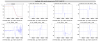
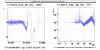
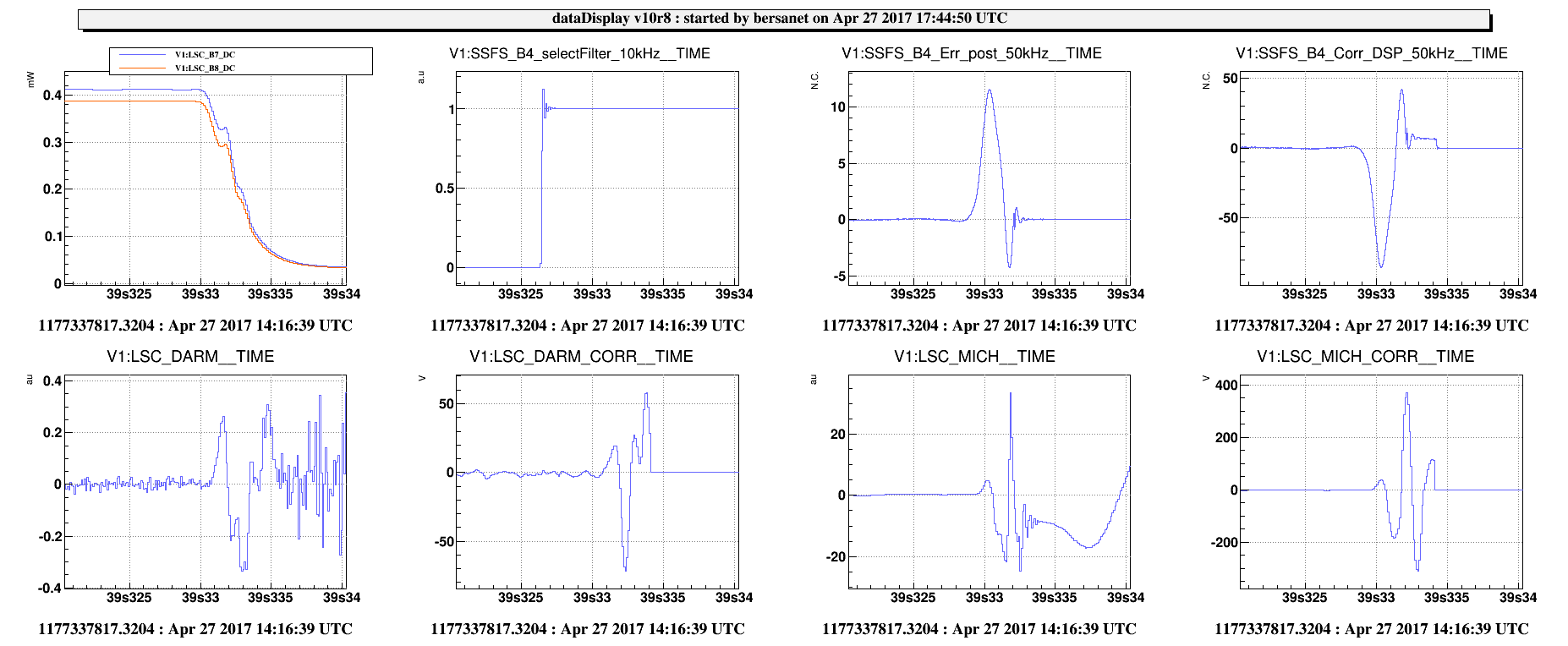
- we started by testing the analog boost, but its engagement made the MC to unlock very abruptly (see Figure 1);
-
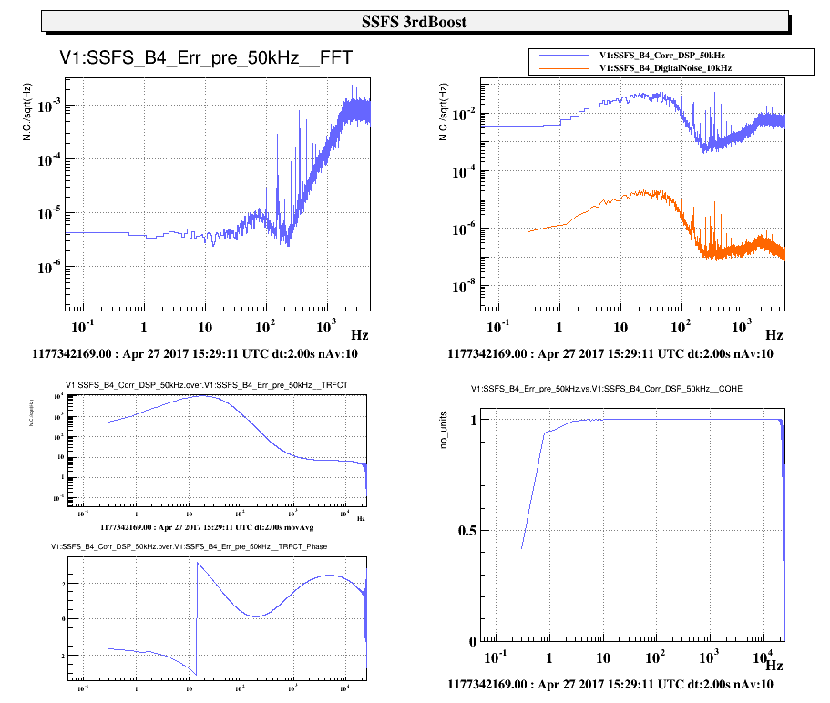
we then decided to go back to the digital boost configuration, and test again all three boost filters (order 1, 2 and 3, the latter one exactly identical to the analog boost):
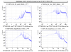
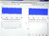
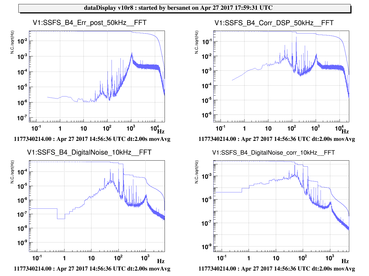
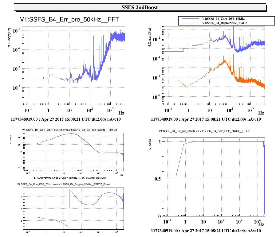
- in Figure 2 there are the SSFS spectra the first time we tried the 2nd order boost, and we found out by the 1 kHz gain peaking that the SSFS gain was too low in this case; we had to increase it for the test of both the 2nd and 3rd order boosts;
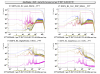
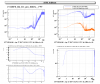
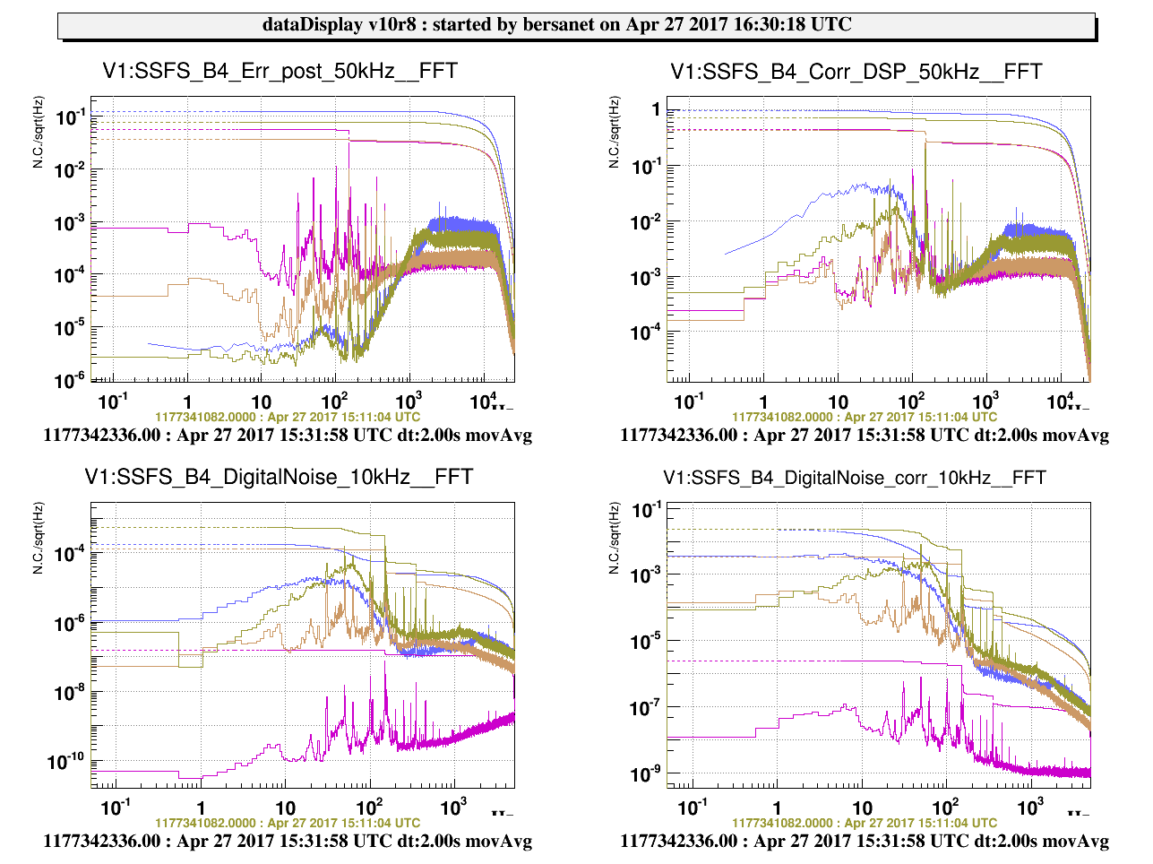
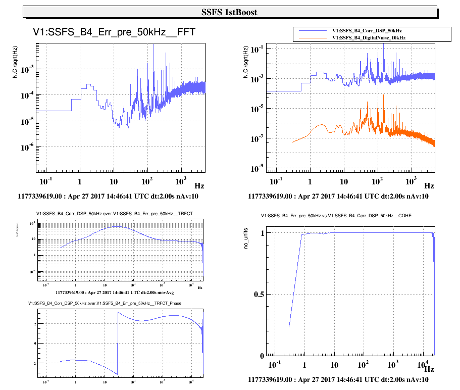
- in Figure 3 there is the comparison of the four test cases, where we used the nominal gain (B4_GAIN = 300) for the boost off and 1st order boost cases; for the 2nd and 3rd order boost we respectively used B4_GAIN = 600 (x2) and 900 (x3), hence the increase of the noise level above 1 kHz; we can see that the 1st order boost test resembles the tests that were done during the weekend; but the 2nd and 3rd order cases show that SSFS_Corr is much higher;
-
at this point we re-set up the analog boost path and tried again to test it, using the B4_GAIN that the equivalent digital boost test proved to be the correct one;
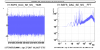
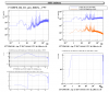
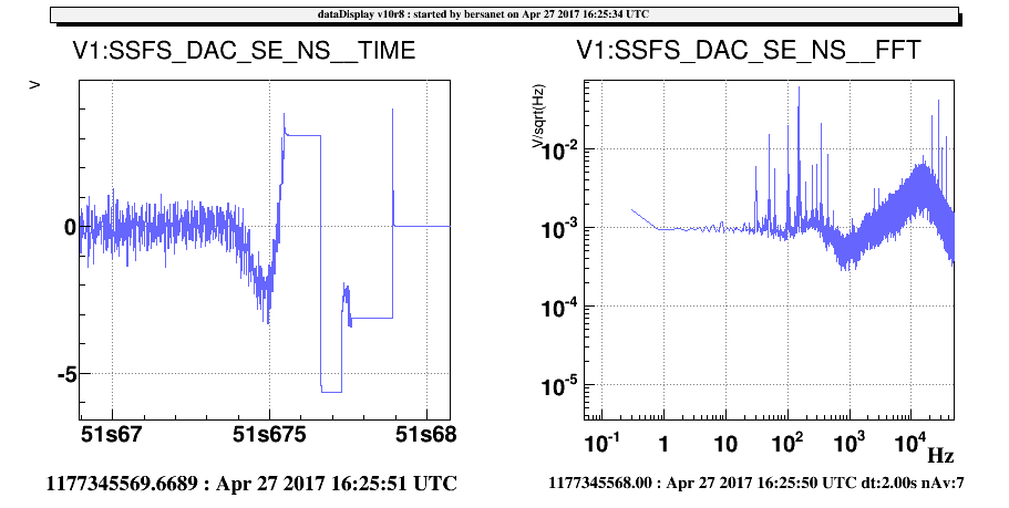
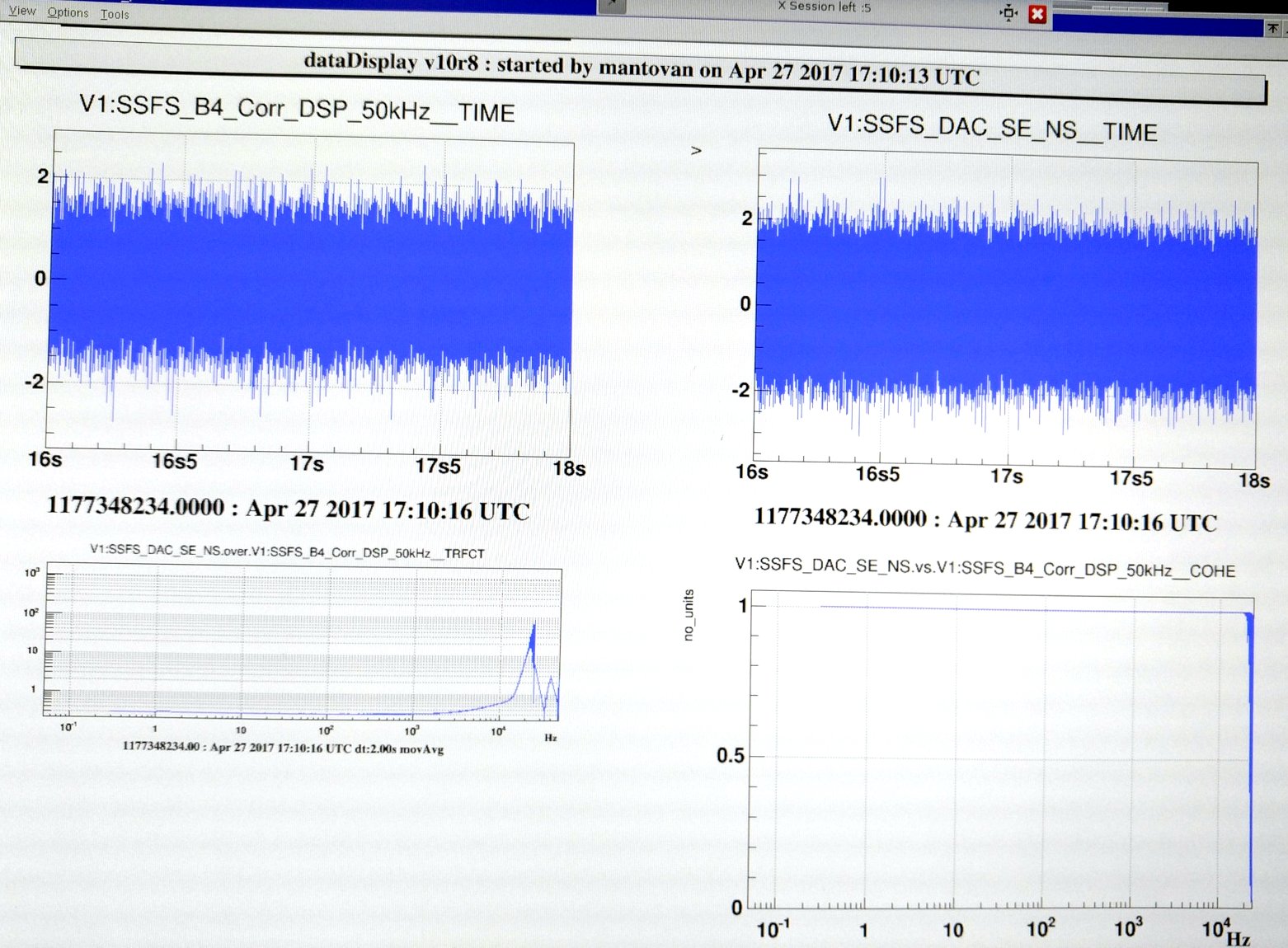
- before doing this test we decided also to have the RampeAuto "SSFS monitor" output monitoring available in the frames by temporarily connecting it to the SSFS DAQbox ADC (name SSFS_DAC_SE_NS) in order to check out the correction due to the analog boost; in Figure 4 there is an example of such channel when the analog boost was off;
- this proved unsuccessfull as well, for the same reason as our first test; but we noticed a very strange saturation on the monitoring channel at the moment of the switch on of the boost (see Figure 5);
- as a last check, we did some driving noise injection on the SSFS with the loop open (but the analog boost on) in order to measure the transfer function between SSFS_Corr and the RFC error signal (while its loop was closed, and the mode cleaner was tricked into believing that nothing was happening on the SSFS side);
- in Figure 6 there is a plot of a transfer function measurement between the input of the analog boost box and the RampeAuto monitor channel (which still has a constant calibration factor): we lost the phase information because of a dataDisplay misbehaviour, but the complete flatness of the TF at low frequency, where the boost should have enhanced the injected noise, indicates some problem;
It would be necessary to some more deep and time-consuming measurements and analysis to figure out what is going on with the analog boost test, but it is unclear if this is a viable activity in our current time frame.
