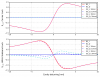
Tonight we collected some data to measure the PRC length. The method is the same one as used at LIGO: the difference in demod phase between CITF locked on the carrier and sideband should be 180deg, and any mis-tuning of the PRC length that moves the sidebands away from resonance will mix the I and Q phase signals, which will be observable in a shift of the demod phase difference away from 180deg.
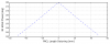
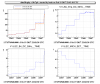
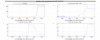
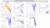
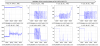
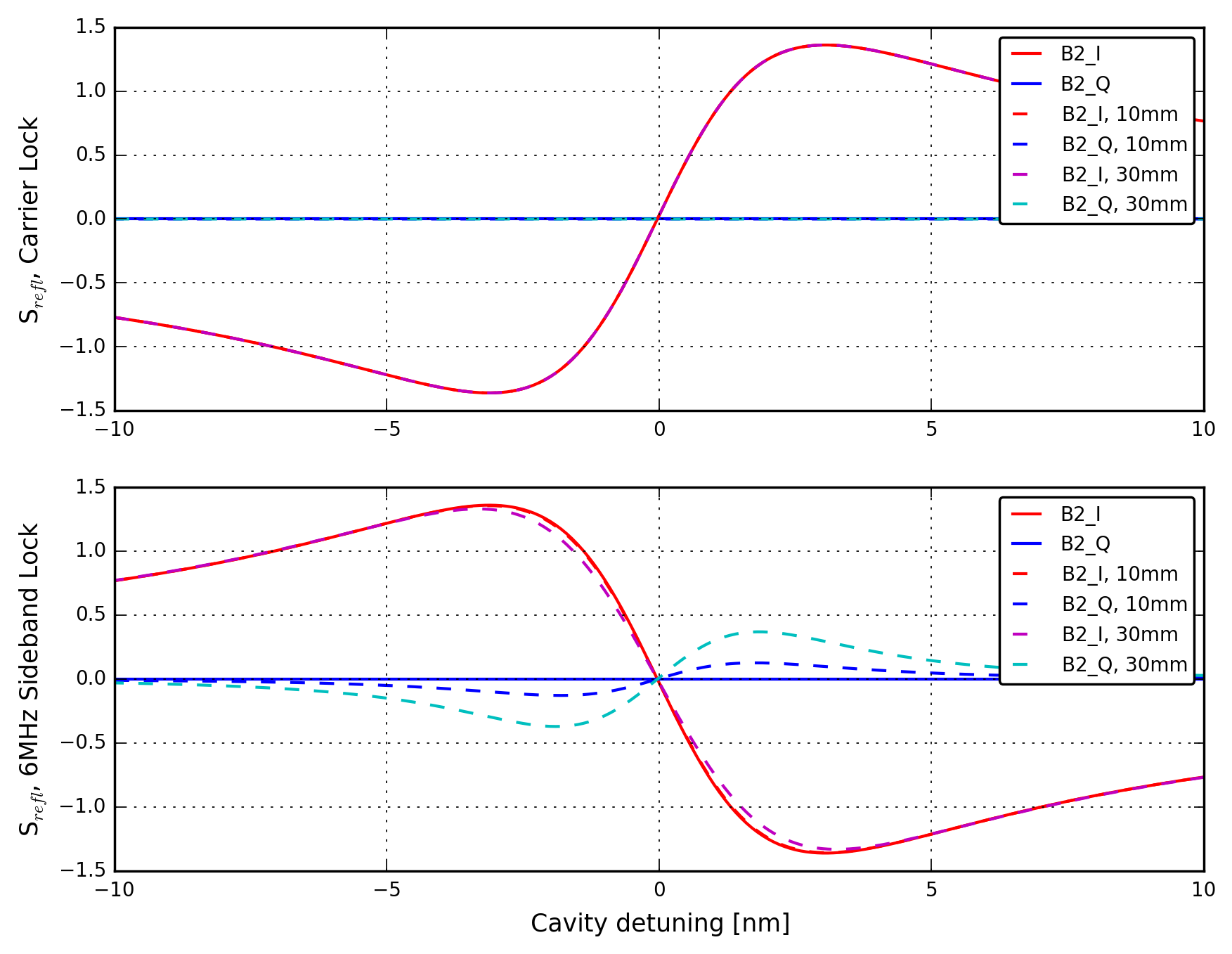
In Figure 1, we demonstrate the effect of a change in PRC length on the B2 6MHz signal. The carrier error signal (which depends only on the microscopic length of the PRC) will always have perfect demodulation, independent of the macroscopic PRC length. But the sideband lock (lower panel) will rotate I into Q if the PRC length is not ideal. In Figure 2, we show the dependence of demod phase on PRC length detuning. The sensitivity is about 8deg per cm, for the 6MHz signal.
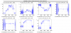
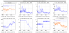
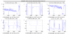
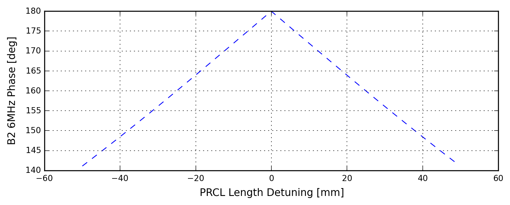
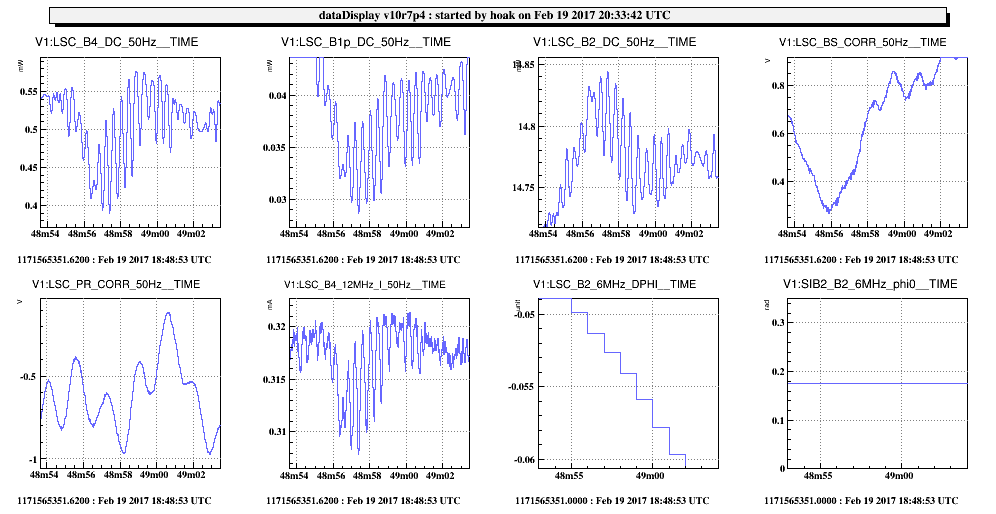
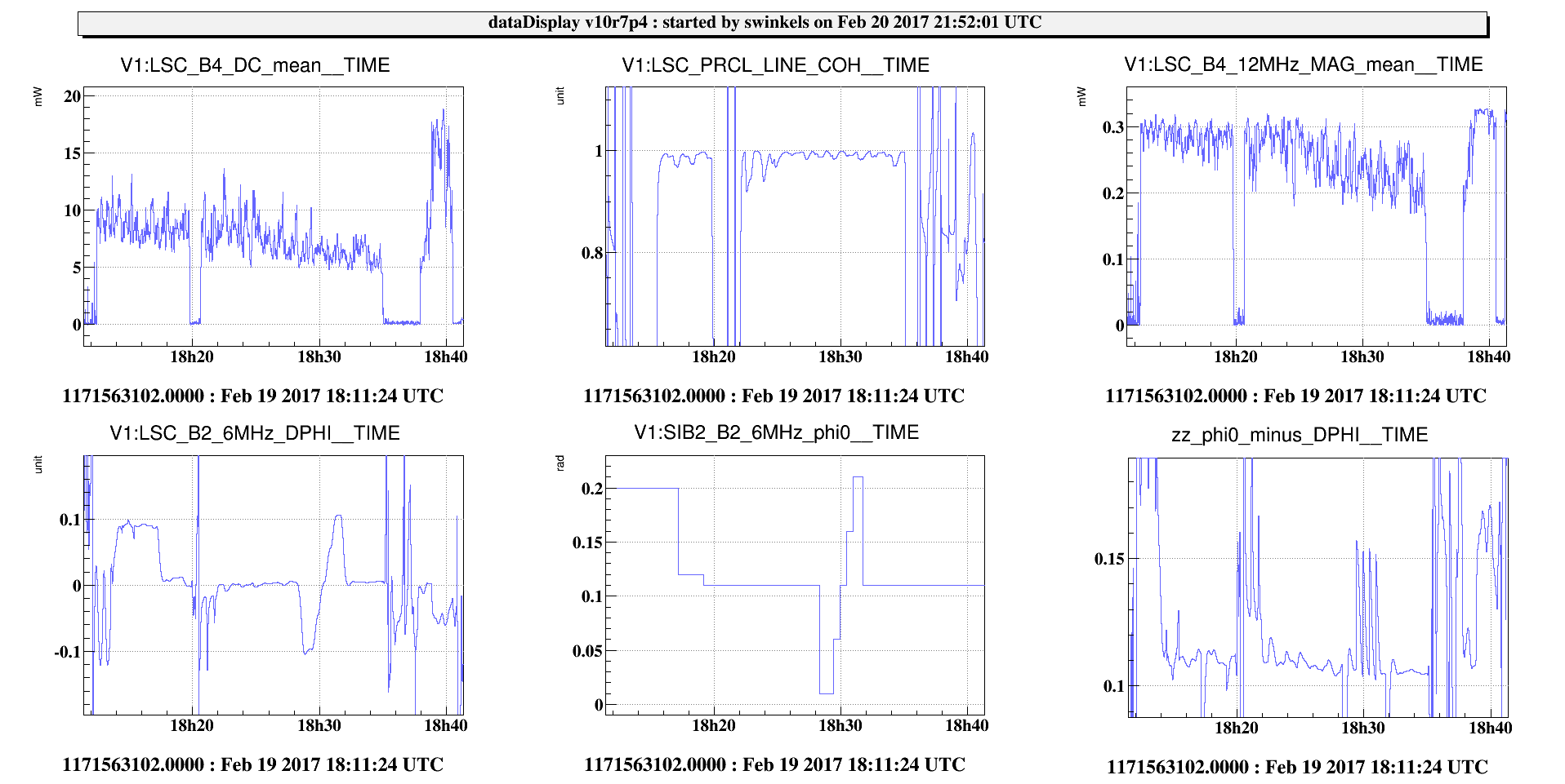
We locked the CITF on both the carrier and the sideband, and measured the demod phase using the PRCL line injection at 67.1 Hz. The quality of the CITF lock is much better than the last time I tried it, I think because of the various suspension improvements (snails, WI) that have happened in the last month. In Figure 3 there is a particularly good lock stretch with CITF locked on the carrier, during which we optimized the alignment by hand. The maximum buildup of 19mW on B4 DC corresponds to ~340W in the PRC.
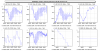
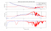
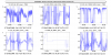
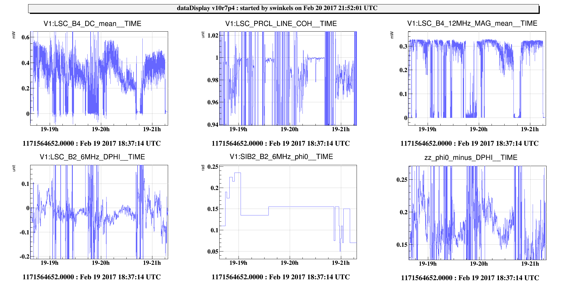
Our measurement of the carrier worked very well (ideal demod phase = 0.11rad), but the sideband lock was too noisy; there were many glitches, and the optical gain was fluctuating by large margins. We're not sure why, but there was a dramatic ~2.2Hz oscillation in either TX or vertical that seemed larger when the sideband was resonating, which appeared in all the DC channels but none of the MAR or MIR channels, see Figure 4 for a burst of this noise. We will look at the data offline, but we might need to improve the sideband locking in order to get a clear measurement of the PRCL length with <1cm precision. During our measurements we saw no evidence that the demod phase was different by more than 10deg, but the results are inconclusive.
Note, to lock on the sideband, we rotated the B2 6MHz demod phase by pi, and rotated the trigger channel (B4 12MHz) by pi to move the sideband flashes to the positive side. The gains of MICH and PRCL decreased by about 40x. Currently the parameters stored in the ini files are for the sideband lock.
While we were working with CITF, the controls for NE opened due to a problem with the SLED, similar to yesterday. With Ettore on the phone we reset the power module and things went back to normal.
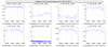
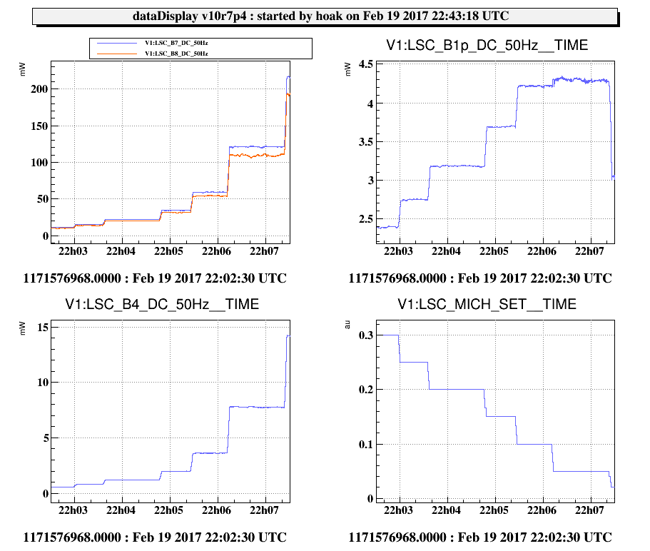
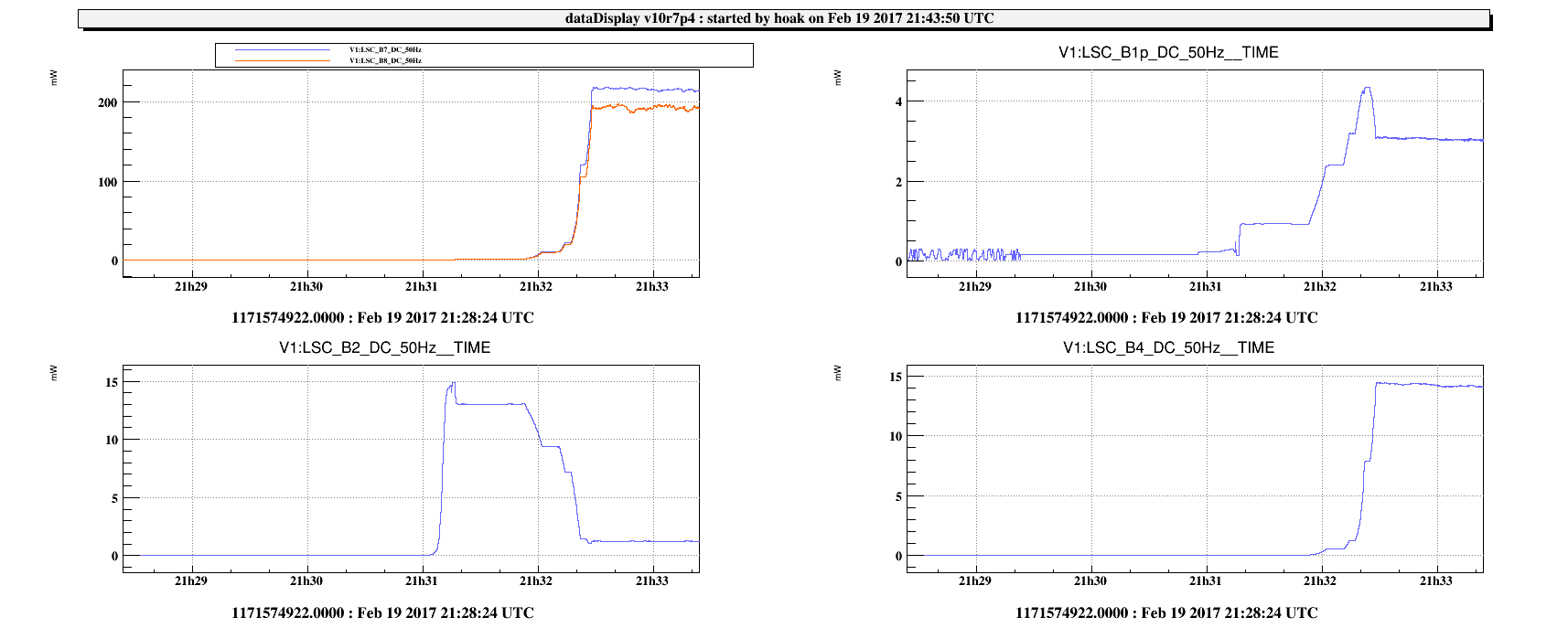
Later tonight we relocked the PRITF and stepped through the later stages of the MICH offset reduction, to collect data for sideband buildup studies. See Figure 5.
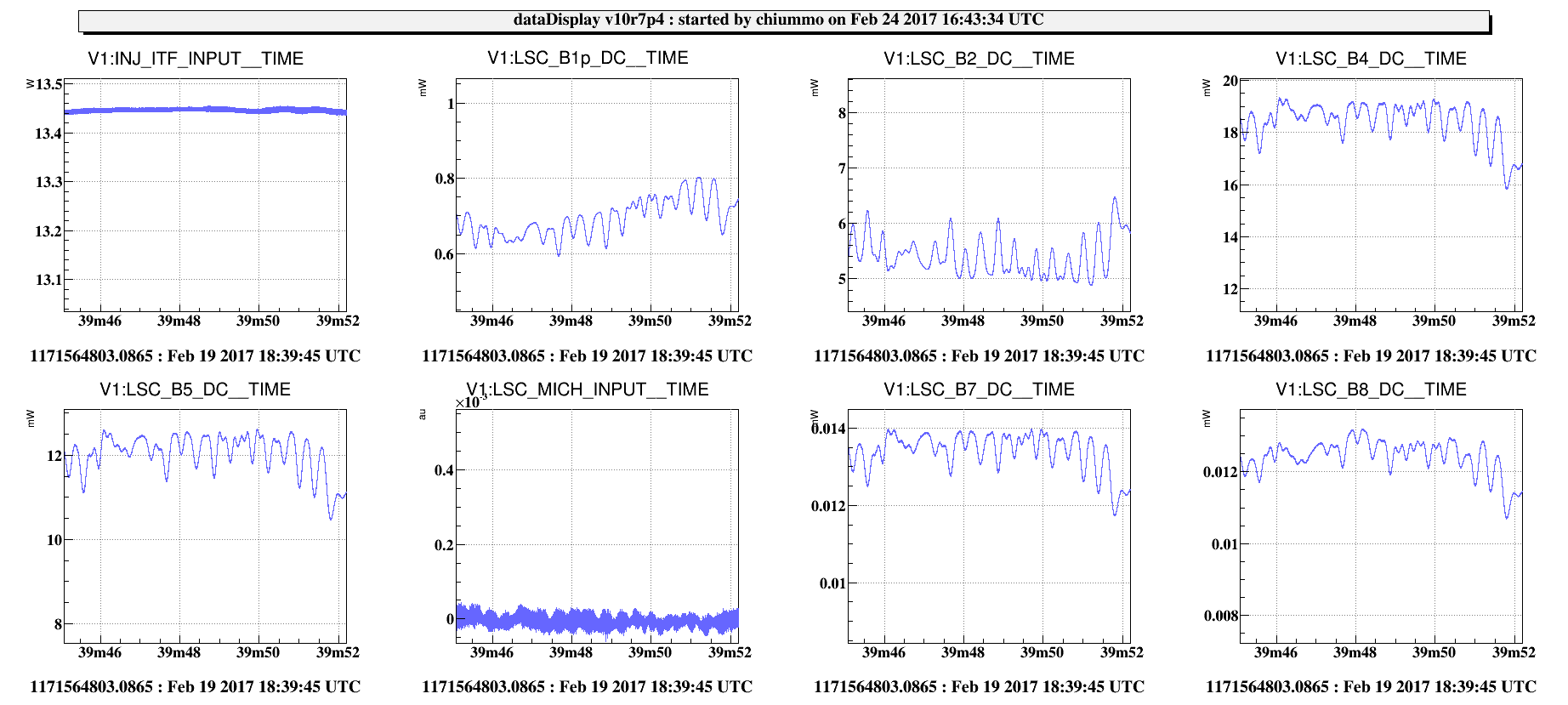
The overall MICH offset reduction sequence is one of the fastest parts of the lock acquisition; the very slow steps are the RFC relocking (sometimes, not always), the CARM_TO_MC step (this is much too long), and the SSFS_ON step. Also the CHECK_QUADRANTS step takes more time than we probably need. In Figure 6, you can see the buildup in powers as we go from arms --> PRITF at 98% dark fringe. You can see the turnover in the B1p DC power, and just barely see the minimum in B2 DC as we pass the critical coupling point.
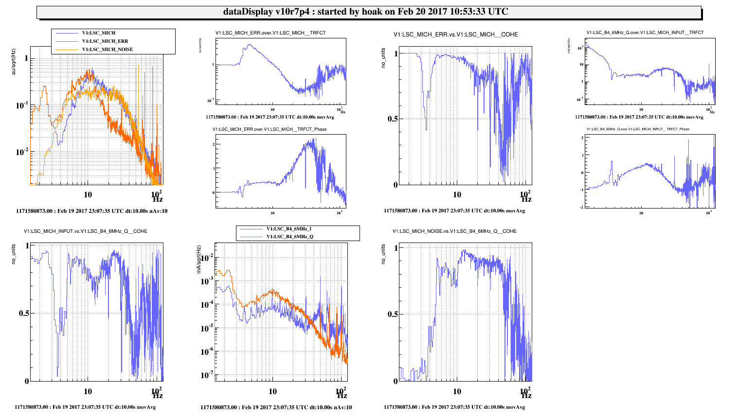
Starting at 23:04 UTC I handed DARM to B1p and made a nosie injection to MICH to measure the B4 6MHz Q transfer function, at 98% dark fringe. At 23:10 I began touching the BS alignment, to correct the strange shape that it acquires after the DARM transition. The alignment adjustment to the BS made the arm powers smoother (reduced the coupling of alignment noise?), but the offset on B4 6MHz Q grew worse, and grew in proportion to the 2f signal, see Figure 7. I also tried applying a DARM offset, but this didn't change the B4 6MHz Q offset.