At the NI, we also checked the sensitivity to a miscentering of the beam on the mirror, which might prove that the coupling is caused by a rotation of the mirror. To obtain the miscentering, Paolo added an offset to the quadrants used for the common end alignment, both in x and y. This was repeated 3 times for the different orientations of the coil, see fig 1.
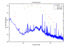
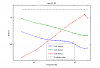
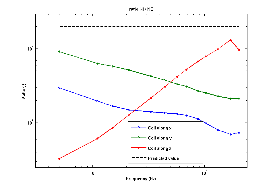
Fig 2, 3 and 4 shows a comparison of the lines in B1 between NI and NE, for the coil aligned along X, Y and Z. Fig 5 shows the ratio between the amplitude of the lines of NI and NE. According to old wisdom, this ratio should roughly be a (frequency independent?) factor of 20, due to the orientation of the magnets on the two mirrors (parallel vs antiparallel). In practice, the ratio is never larger than 10 and has a different frequency dependency for the different axis. It will require some time to do the full analysis and interpretation of these results.


Injections at the NI mirror:
====================
Hall probe at x = -2m, y=0, z=0 (in mirror ref. system)
Hall probe channel names:
Pr_SE_DetBrew2 = horizontal, along mirror X
Pr_SE_DetRack = horizontal, along mirror Z
Pr_SE_WallCE = vertical
Hall probe calibration: 1V/Gauss
1) coil axis along X
>>> check linearity:
inject 11Hz line with three different values of Voltage to the coil:
freq[Hz], voltage[Vrms], current[dBVr], GPS
11, 30, -30.7, 887098575
11, 10, -27.7, 887098859
11, 3, -21.7, 887098859
>>> lines injections (all with 30Vrms):
[Hz], current [dBVr], GPS
11, -30.7, 887098575
15, -33.1, 887099189
21, -35.5, 887099316
33, -38.0, 887099410
44, -39.8, 887099506
57, -41.8, 887099606
69, -43.3, 887099731
87, -45.2, 887099855
103, -46.6, 887100022
132, -48.8, 887100117
171, -51.1, 887100284
203, NA, 887100425 to 887100605
5, -26.1 887100637
(current in coil [Ampere] = 10^(dBVr/20))
2) coil axis along Z
(30Vrms to the coil)
[Hz] GPS
5 887100919
11 887101081
15 887101170
21 887101266
33 887101369
44 887101467
57 887101571
69 887101670
87 887101782
103 887101890
132 887101987
171 887102096
203 887102209
3) coil axis along Y (30Vrms to the coil)
5, 887102403
11, 887102511
15, 887102608
21, 887102723
33, 887102823
44, 887102906
57, 887103010
69, 887103111
87, 887103204
103, 887103324
(163, 887103409, 45s)
132, 887103476
171, 887103553
203, 887103656 to 887103783
>>> beam translation experiments: Oo_B5_q1x, Oo_B5_q1y
15Hz line
1) coil axis along Y
ramps +3mm -> -6mm -> 0
ramp x from 887104441 to 887105965
ramp y from 887106155 to 887107070 (10:36:45 UTC)
2) coil axis along Z
smaller excursion to save time
ramps +2mm -> -4mm -> 0
ramp x from 10:39:30 UTC to 887107707 (10:48 UTC)
ramp y from 10:51:00 UTC to 10:57:30 UTC
3) 887108357 coil along X
ramps +2mm -> -4mm -> 0
ramp x from 11:00 UTC to 11:07 UTC
ramp y from ... to 11:25:30 UTC
Injections at NE mirror:
==================
Hall probe at: x = -2m, y=0, z=0 (in mirror ref. system)
Pr_B7_d2_ACq = along X
Pr_B7_d2_ACp = along beam (Z)
Pr_B7_d1_ACq = vertical (Y)
1) coil axis along X
Hz dBVr GPS
5 -26.3 887116792
11 -30.7 887116937
15 -33.0 887117014
21 -35.4 887117103
33 -38.4 887117194
44 -40.6 887117293
57 -42.7 887117391
69 -44.3 887117487
87 -46.2 887117583
103 -47.5 887117700
132 -49.8 887117820
171 -52.1 887117909
203 NA 887118025
(current in coil [Ampere] = 10^(dBVr/20))
2) coil axis along Z
Hz GPS
5 887118162
11 887118273
15 887118372
21 887118481
33 887118582
44 887118681
57 887118796
69 887118896
87 887118976
103 887119074
132 887119164
171 887119270
203 887119372 to 887119600
3) coil axis along Y
Hz GPS
5 887119677
11 887119796
15 887119895
21 887119995
33 887120081
44 887120178
57 887120279
69 887120368
87 887120470
103 887120574
132 887120666
171 887120770
203 887120866 to 887120961