People entering: Erbanni, Francescon, Menzione, Pasqualetti, Zaza
ITF found DOWN in UPGRADING mode.
Below the list of the activities communicated in control room:
- NI instrumented baffle installation - https://logbook.virgo-gw.eu/virgo/?r=69224
- removal of the WI baffle - https://logbook.virgo-gw.eu/virgo/?r=69225
- in the afternoon the INJ team worked at BPL calibration
Noel Delgado, Jose Ferrer, Otger Ballester and Alex Carmona will go in.
Preliminary measurements
On June 10 and 11 we installed the setup and performed preliminary measurements in order to check the instrumentation and optimize the measurering setup.
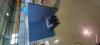
We installed two shakers on the exterior of the NI chamber: the large shaker is placed om the NI tower base, NW corner, and the small shaker clamped to the North big flange (thank you Antonio for helping in this installation). The shakers (in turn, manually) are connected to the amplifier which is driven from a DAC ch in the TCS room.
After a careful cleaning of all the tools, we moved inside the NI.
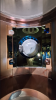
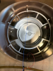
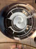
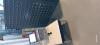
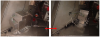
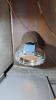
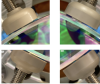
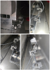
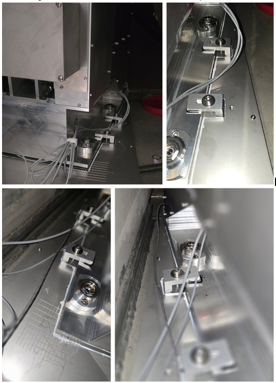
As a test we performed measurement of mechanical modes of the the frame shown in Figure 1. We used the monoaxial accelerometer PCB352C68 on the vacuum chamber (attached with double tape, which Antonio aknowledged, asking for a careful cleaning with Acetone) and the triaxial accelerometer PCB356B18 ("golden cube") attached to the frame in different positions, aslo with double tape. For the data acquisition we used the CoCo80X.
We tested (the full set of measurements is detailed in the attached .txt file):
- injecting different levels of colored noise 10-1200 Hz to the shaker (0.02,0.03,0.04 V). For reference, inside ENVnoise.cfg:
ACL_NOISE_CH noise_white "V" 5 SAMP_FREQ 1.0
ACL_FILTER_CH noise_colored "V" 5 SAMP_FREQ noise_white 0.03 "flt3"
and inside ENVnoise_Filters.cfg:
ACL_FILTER_SET "flt3" 1 1 600 20 # --> sets gain 1 @ f0 Hz (must be the same f0)
ACL_FILTER_BUTTERWORTH "flt3" "bandpass" 4 3 600 590 - use of the small or the big shaker
- two configurations for the monoaxial acc: vertical or horizontal (see pictures)
- two positions of the cube acc. on the frame: (1) inner ring, (2) outer ring close to holding point
For each configuration we measured the TF of the monoaxial acc versus each axis (X,Y,Z) of the gold cube acc, and compared.
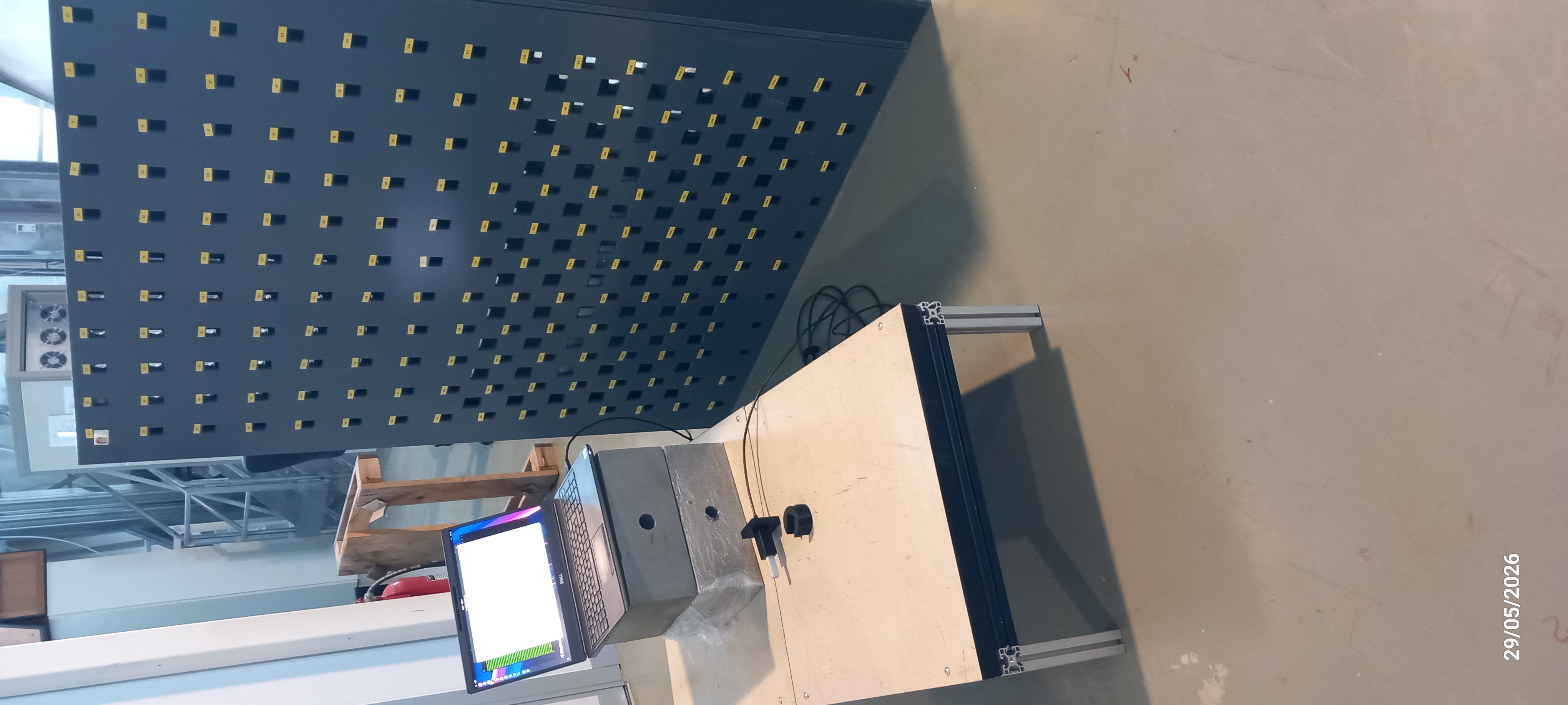
Figures 1-3 are pictures of the frame with accelerometers in different positions.
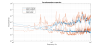
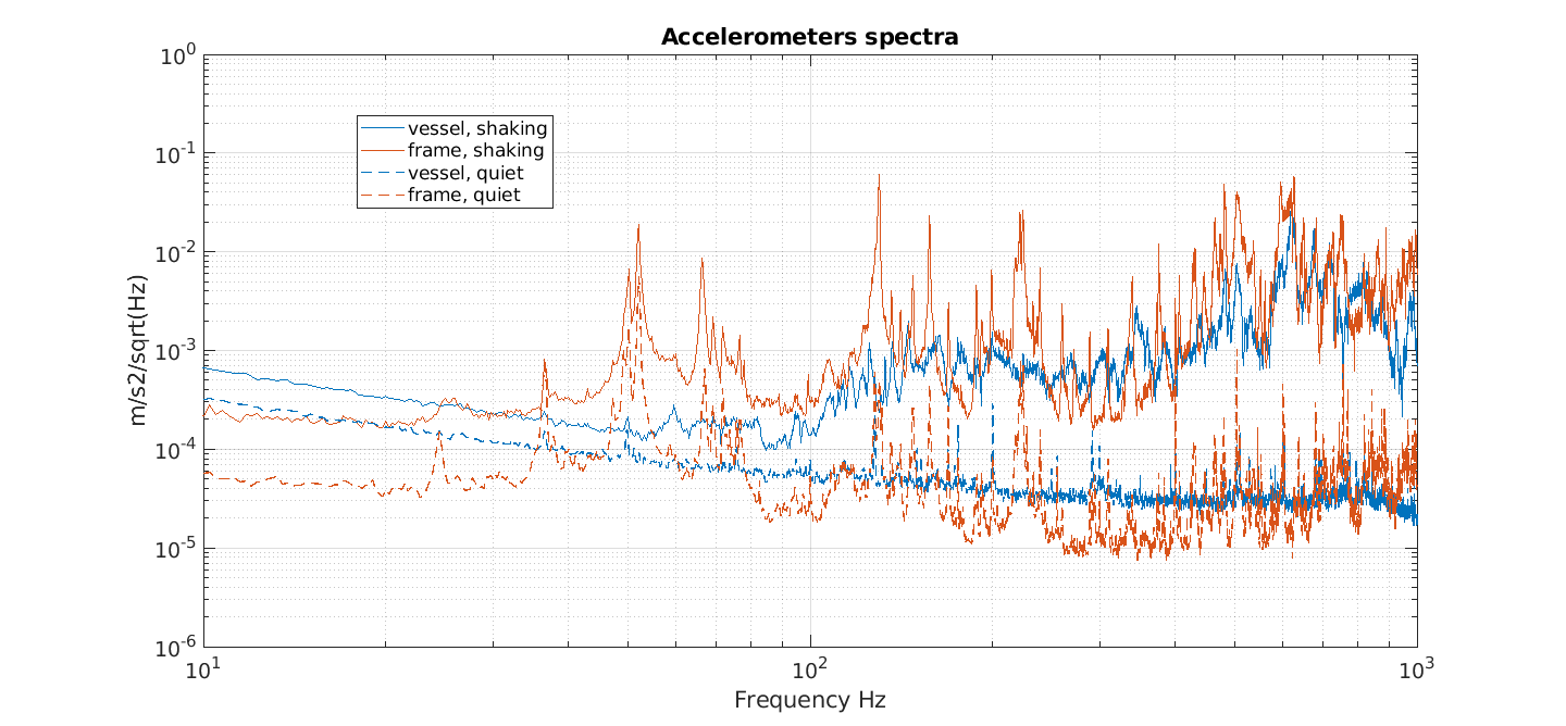
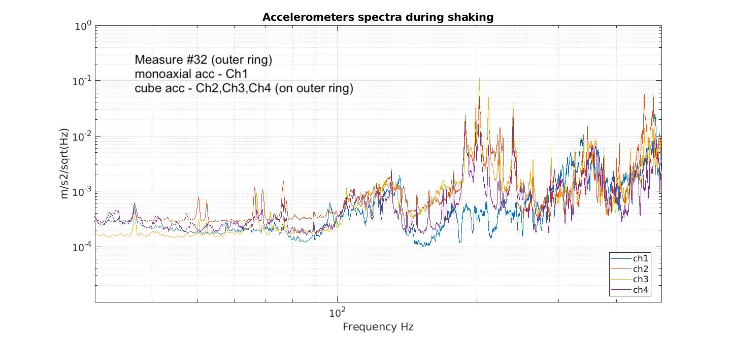
Figure 4 compares spectra during quiet and during shaking. The shakers were able to excite above the quiet noise in the whole expected range.
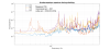
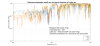
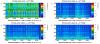
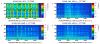
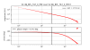
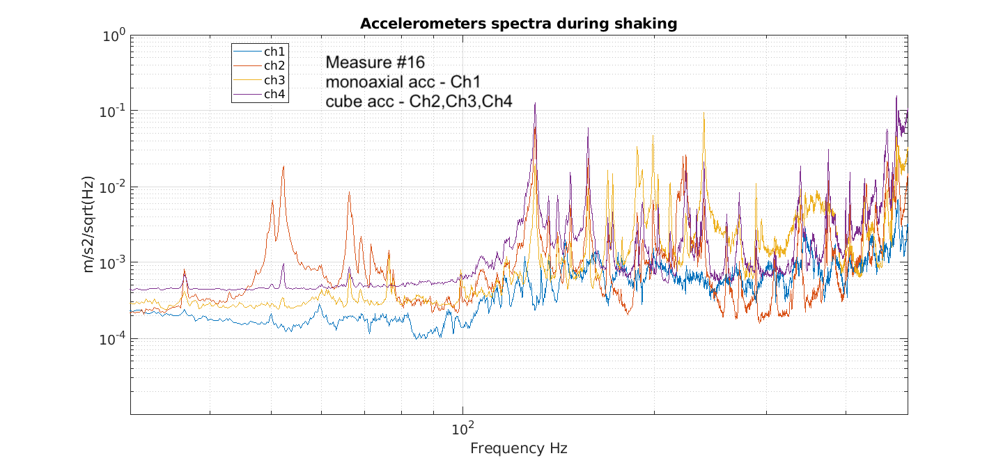
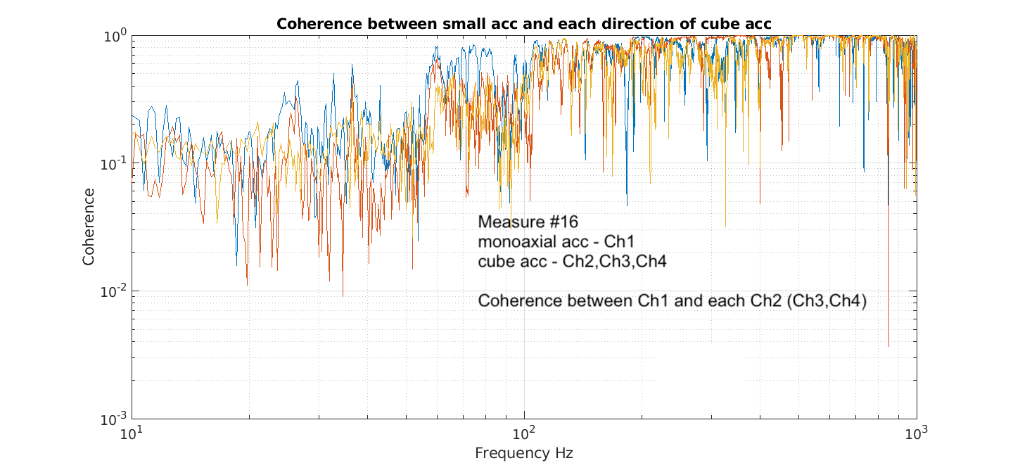
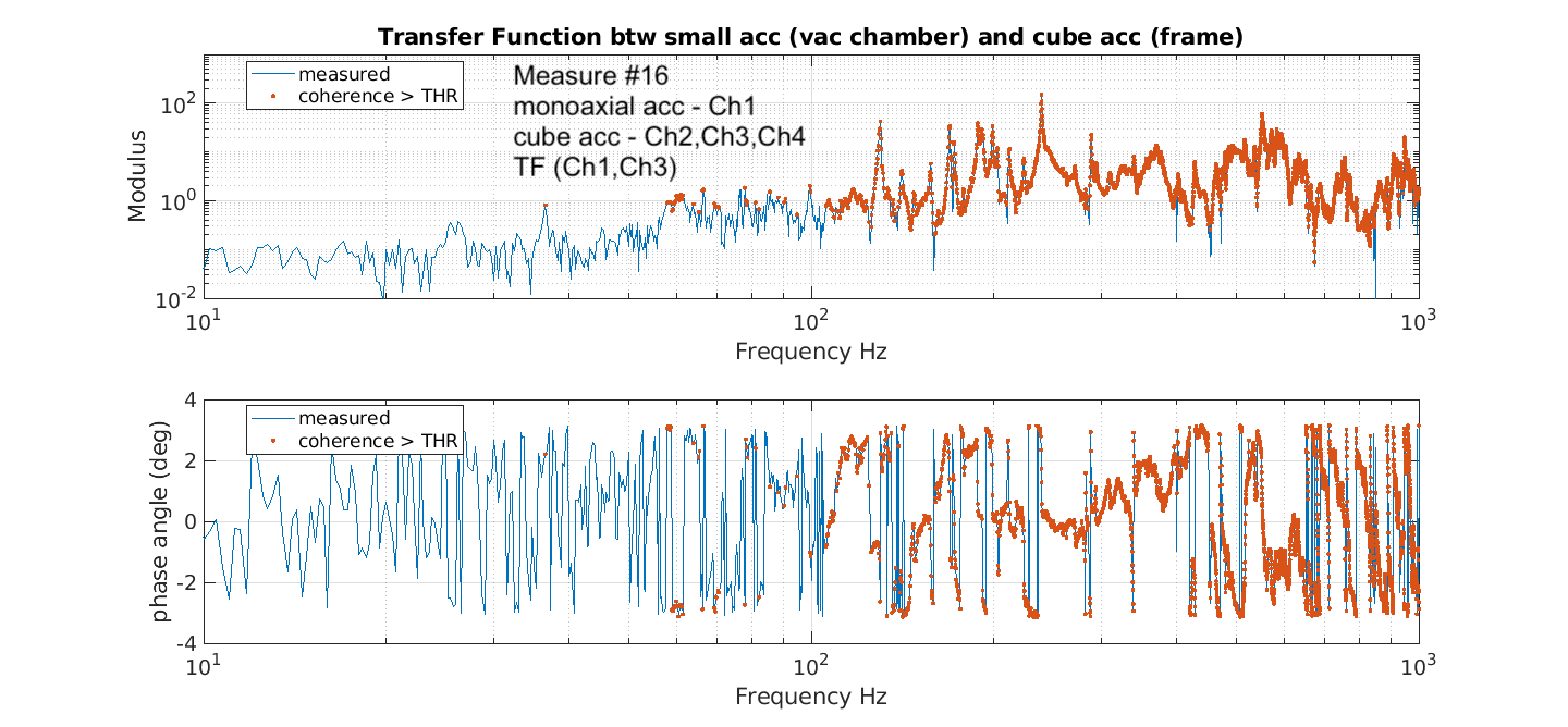
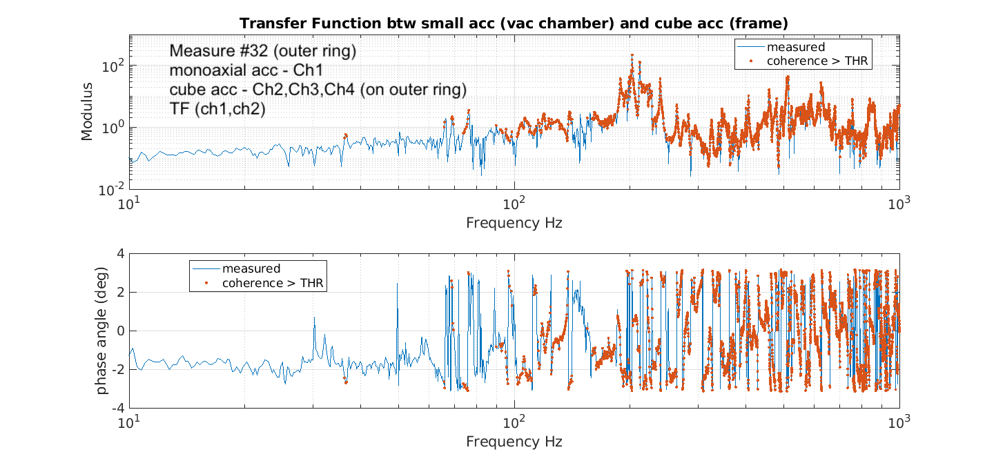
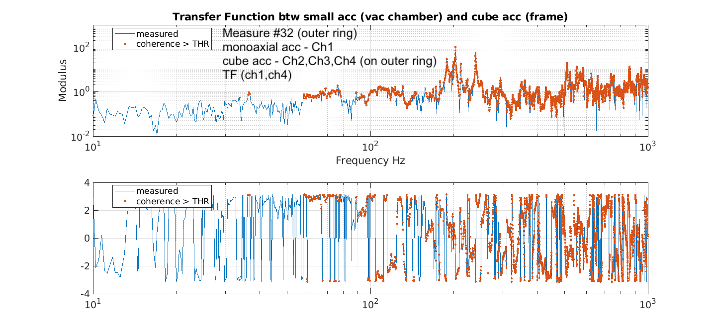
Figures 5-9 refer to the setup with monoaxial acc. horizontally placed on the vessel and the cube acc on the inner ring of the frame. They show: spectra, coherence, TF between monoaxial acc and each of the three direction of the cube acc.
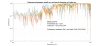
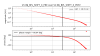
Figures 10-end is the same set, but when the cube acc. was positioned on the outer ring of the frame, near to the frame's holding point.
Measurements were satisfactory, the setup works.
A number of peaks were excited especially in the range 50Hz to a few hundred Hz. Good coherence is measured in this range.
TFs look satisfactory: we observe phase rotation in correspondence of the main excited modes. The red points in the TF plots correspond to coherence > 0.4.
Moving the cube accelerometer from the inner to the outer ring of the frame, some peaks are no longer excited (for example the 130Hz peak is no more observed). As expected, this position is more rigid and low frequencies modes are not easily detectable from here.
Additional observations:
Tests indicate a slightly better preference for using the small shaker, with level 0.03V. The placing of the accelerometer on the vacuum chamber, horizontal or vertical, does not make significant difference in the measured TF.


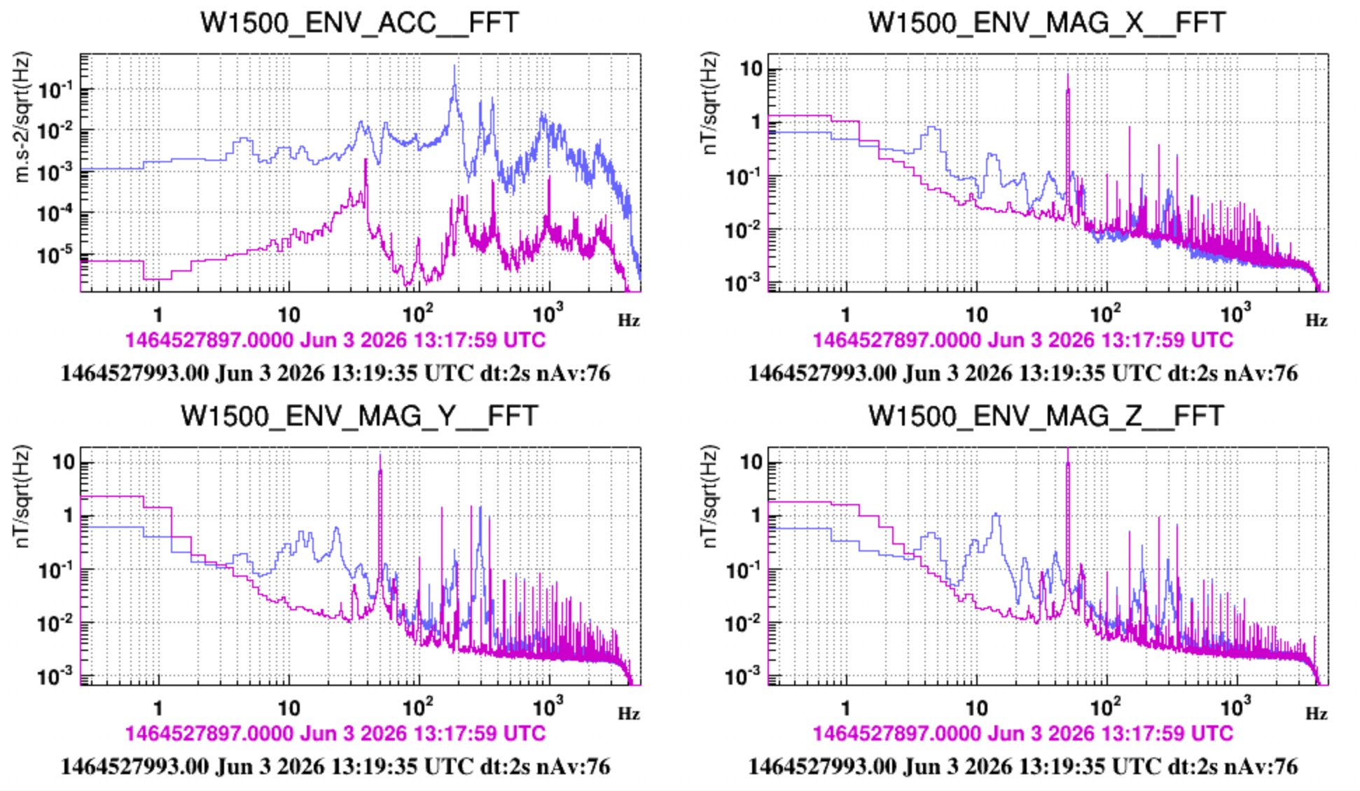
Between May 29 and June 3rd we performed at 1500W noise characterization measurements of two ion pumps, which here we call simply small and big (info on the exact model will be added later on). These pumps consist of a large permanent magnet and the concern is the magnetic noise produced when this pump vibrates withing the static Earth field. A question concerning this noise and the consequent safe distance from the O5 test masses was asked by VAC reviewers. Answering it is the aim of this activities. Two activities have been performed.
1) Mapping.
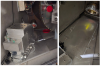
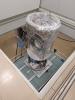
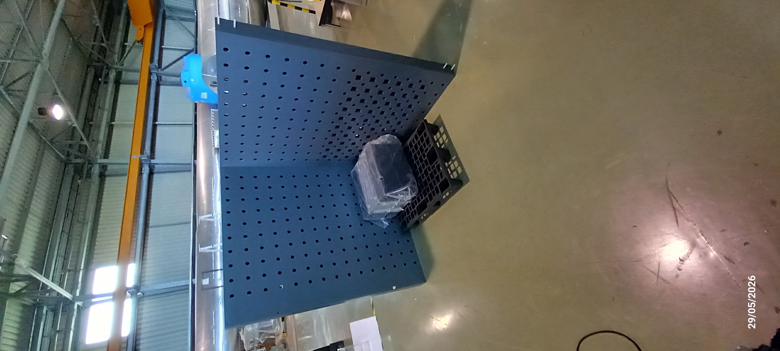
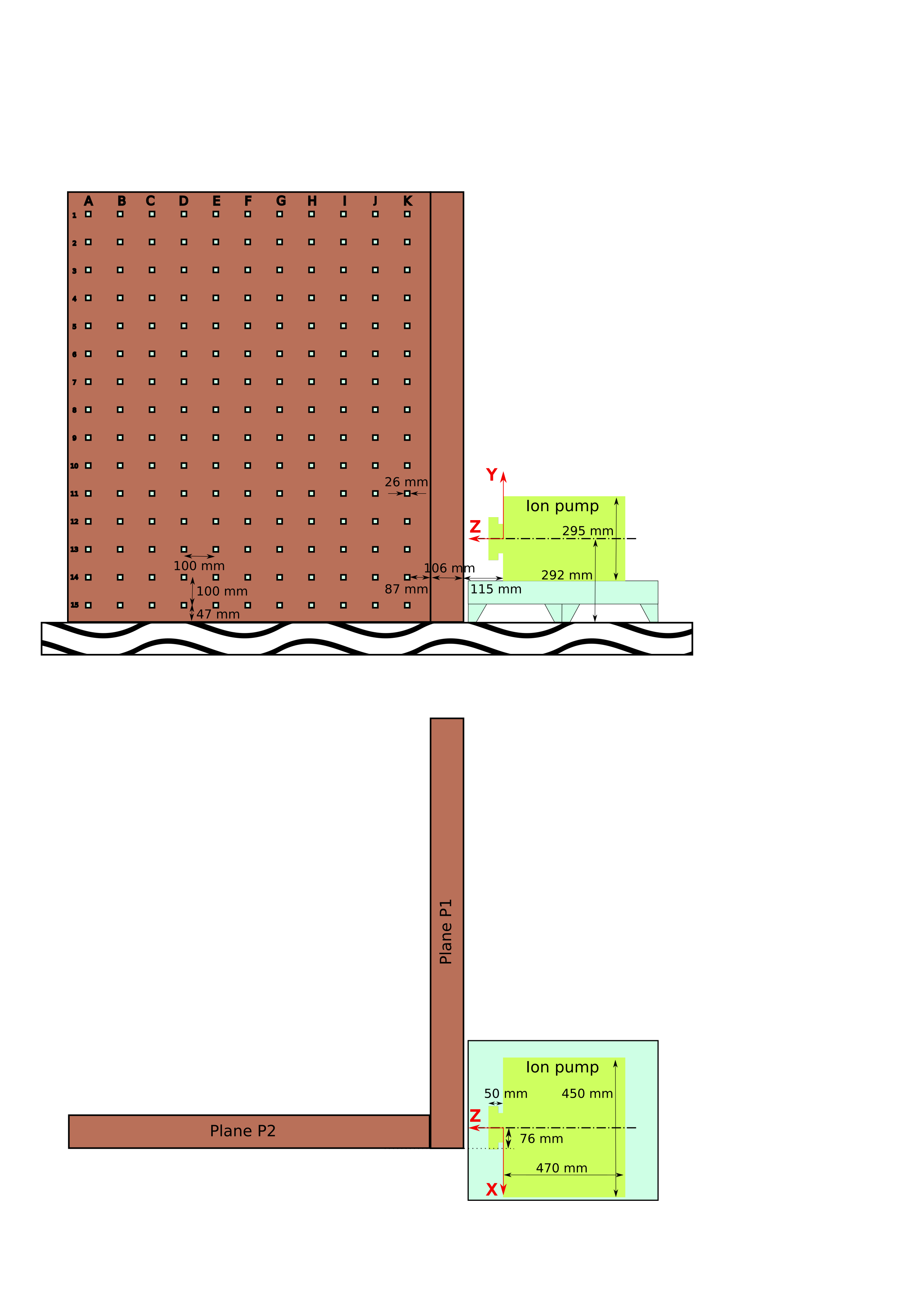
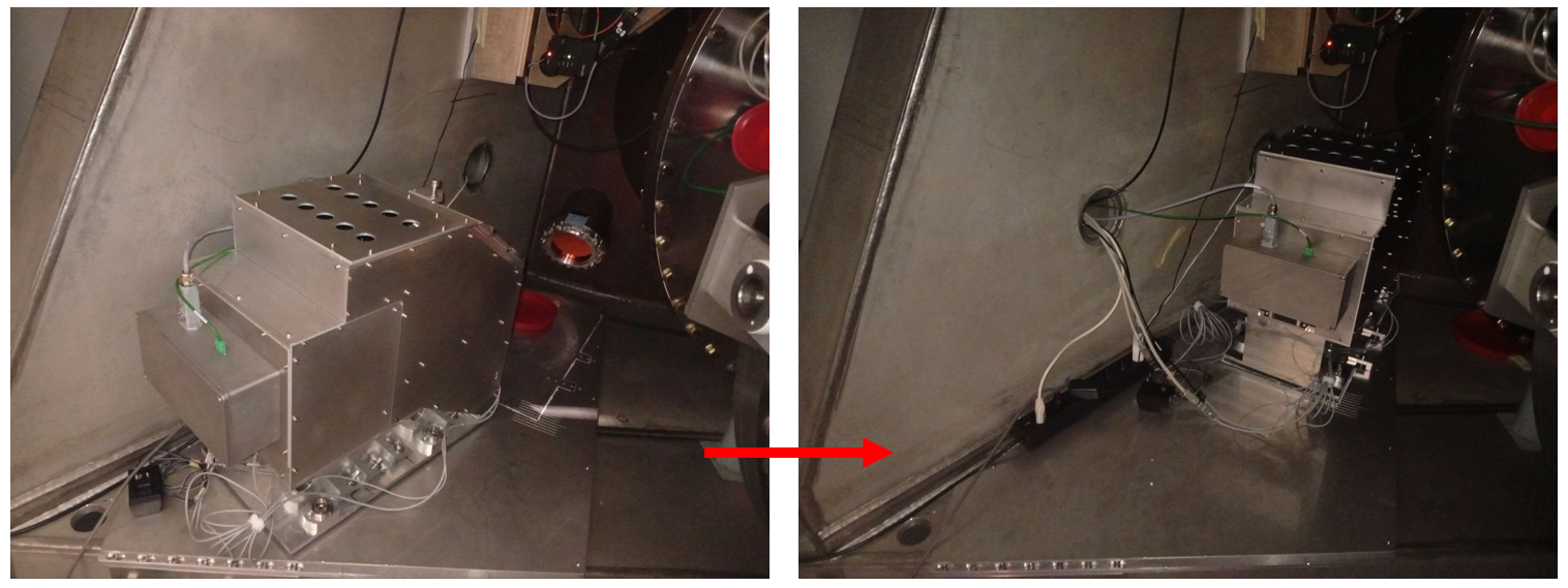
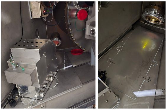
This activity was lead by Gilles who measured the ion pump static field on 3D grid of positions around each pump. For the small pump he used a 2D paper grid, for the big pump he used the plastic perforated frame that INGN-Genova made for the payload magnetic characterization and which the vacuum team moved from the CEB clean rooms to 1500W and reassambled in position. Gilles used his 3-axial magnetic probe, moved along the grid.
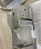
Attachments 1 and 2 show pictures of the setup of the big pump.
2) Shaking.
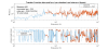
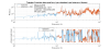
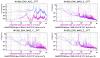
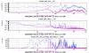
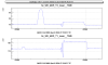
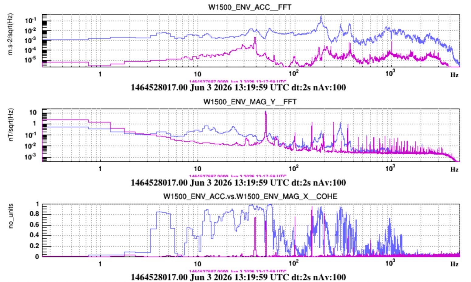
The big pump was excited using a little hammer tapping on the top flange of the ion pump, while one accelerometer (meggit) positioned vertically on top of the pump, and one 3-axial magnetic probe (Bartington MAG03_MC_100) were recording respectively the vibration of the pump body and the magnetic field. The magnetic probe was moved at a number of distances from the pump edge (approx 20cm to 120cm). Figure 3 is a sketch with coordinates of the measuring grid.
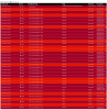
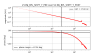
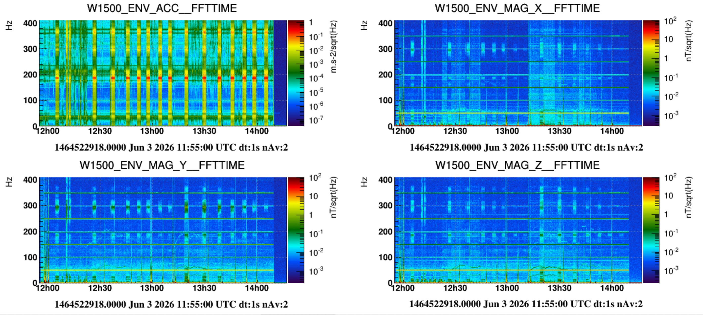
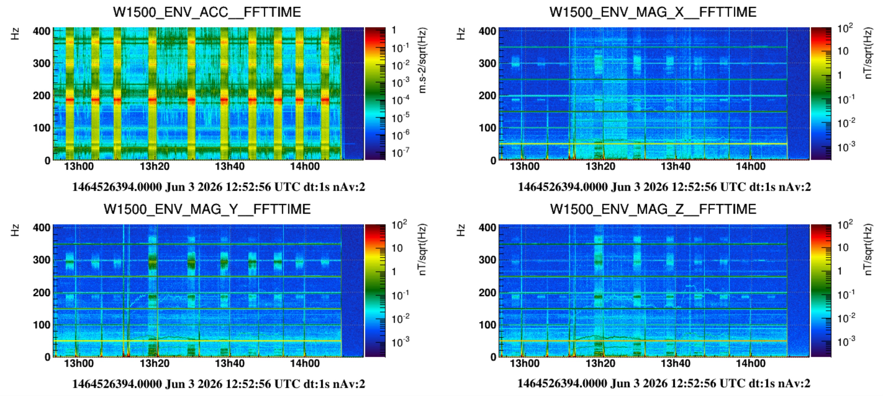
The attached txt file lists all measuring times and associated position of the magnetic probe. Attached are also spectrograms of the full measurement set. A magnetic field noise excess was measured in all locations. The last two show the probes spectrum when at approximately 30cm from the pump edge (mag probe position J13). The excess magnetic noise is evident and is also coherent with the vibration.
Data frames have been saved in /data/procdata/envmon/MagneticNoise/ion_pump/shaking/saved_gwf/ion_pump_shaking_20260603_1464522918_8500.gwf
Analysis will follow.
ITF found DOWN in UPGRADING mode
No activities communicated to the control room
Today around 14:00 UTC, the WI PAM was moved back to its original reference position marked on the alignment plate (see 69208), since it was temporarily moved to allow the replacement of the damaged ZnSe viewport (see 69219).
ITF found DOWN in UPGRADING mode.
All times are UTC.
Below the list of activity comunicated to the control room:
09:03 - 09:56 Gouaty went in CEB Storage Room at 2nd floor, no access to any experimental areas required.
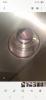
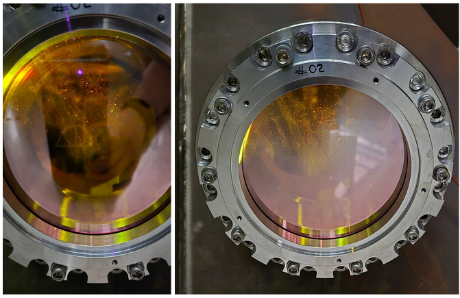
10:10 - 10:39 ZnSe WI viewport inspection (Pasqualetti, Nardecchia, Lumaca, Corubolo).
14:16 Zaza reported that NI payload has been cleaned and the ZnSe viewport has been replaced.
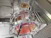
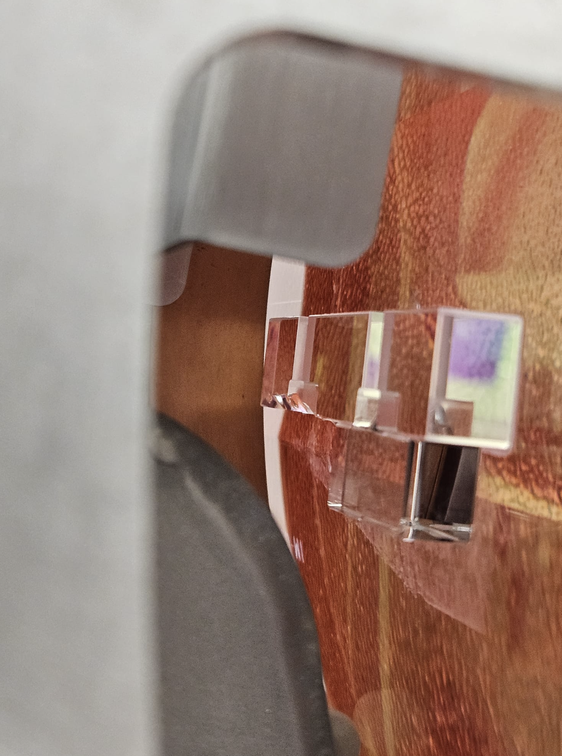
Notice that the safety stops are touching the CP in this case. At the time of the installation of this CP into its mount it was decided to keep them touching for safety reasons given the limited quality of the HCB on one side. We will realize if this measure was actually needed once the CP will be dismounted. Fig. 2, notice that in case of NI, the CP was very firmly fized into its mount and teh HCB strongly acted also in between the metal and the glass, the on both sides in order to detach the mount the fused silica ears underwent to break.
On Tuesday 9/6 morning I was engaged in WI payload works. In the morning with the PAM alignment and in the afternoon with the WI payload extraction.
At 18.30, after the work I visited the status of NI payload, as planned, to have a look and complete the assembly work today.
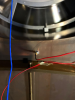
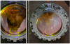
Unfortunately I saw that two fibers were broken. Luca came and took a look on the system. We do not know when the breaking happened.
The ear appears damaged, rather severely.
Today, with Luca, the payload cage was partially dismounted to allow a better access for inspection.
Helios and Flavio in the afternoon of today inspected. Further entries will follow.
Critical points:
- breaking during the assembly or just after are extremely rare
- availability of spare units for anchors
- clean detachment of 3 anchors without damaging the ears
Further entries will follow

The WI payload was then re-wrapped and is currently stored into the CB clean room.
I have released a new version v10r3p4 of VirgoProcessMonitoring, that improves the browsing of the configuration file history. All instances have been restarted to use this new version.
The WI PAM activity has been finished yesterday, and the laser used for that activity was switched off yesterday (Tuesday) at 9:41 UTC as reported in https://logbook.virgo-gw.eu/virgo/?r=69194
ITF found DOWN in UPGRADING mode.
Planned activities communiucated to the control room.
- - Alignment GUI test Al9 (Boldrini, Fiori, Seder)
- - ENV: activitiy for NI instrumented baffle TF measurement (Tringali, Spinicelli, Fiori) in progress...
- - PAY: WI CP mount removal (Majorana, Naticchioni) in progress...
- - TCS: WI PAM actuator position reference and movement, plus viewport external inspection (Corubolo, Nardecchia, Lumaca, Pasqualetti, Gherardini, Francescon)
- - INF: Confined space safety training (Zaza, Gherardini, Fabozzi) in progress in CEB clean rooms
- - DAQ: 15:08 UTC - DMSserver restarted under request of Loic (for PCal flags)
This morning (09:00 - 10:00 LT), we went to the WI base tower to take reference pictures and measurements of the PAM actuator position (see Fig. 1).
Afterwards, we contacted the vacuum team to understand how much clearance is needed for the future replacement of the viewport. We agreed that moving the PAM actuator to a parking position on the base tower would provide sufficient clearance for the planned work. (see Fig. 2).
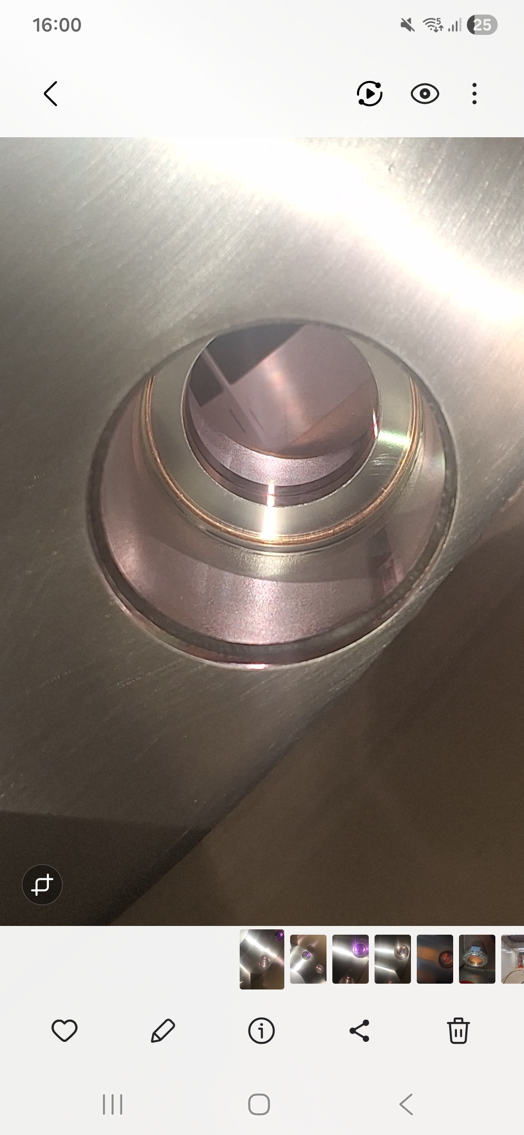
Finally, we took some pictures of the viewport to be replaced, as seen from the outside (Fig. 3). From the outside, the smaller viewport does not show the same signs of degradation as the viewport to be replaced. In particular, no sparkling/glittering features are visible, which would suggest dust or coating flaking, as observed on the damaged viewpor t (69192).
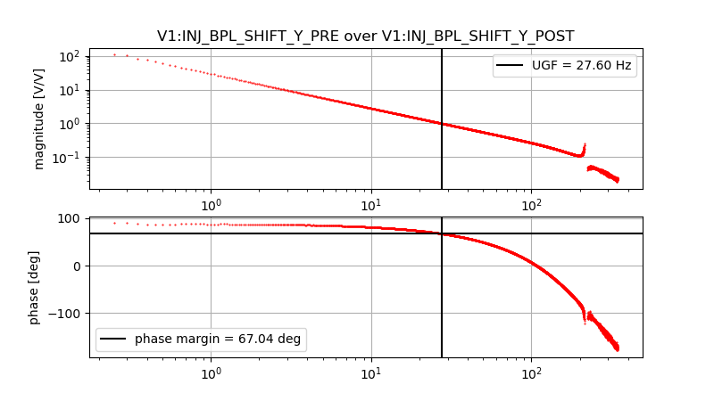
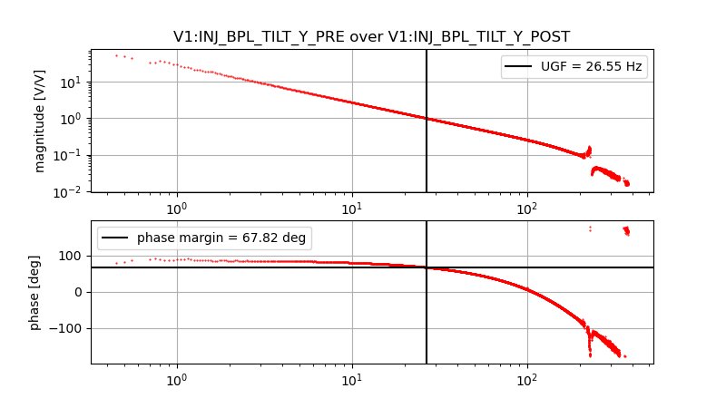
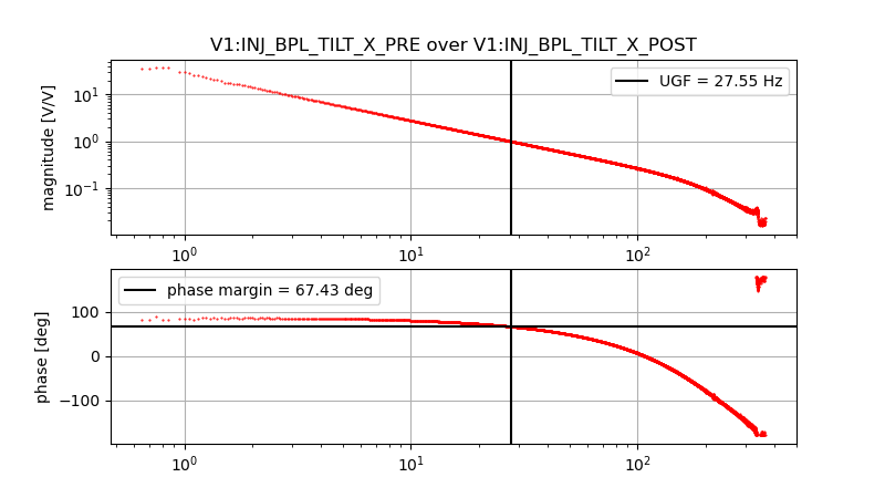
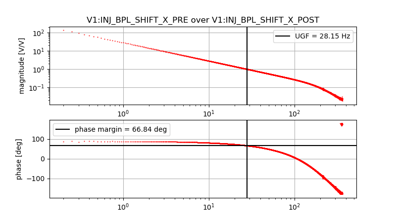
The OLTF of the BPL was measured after the bench was suspended. With the loop closed, a color noise was injected just before the control filter with a 0.01 V amplitude.
The measured UGF is 27 +/- 1 Hz, and the phase margin is 67 +/- 2 deg for all degree of freedom.

The cellophane will be unwrapped and after this partial dismount the payload will be wrapped again.
The WI payload was then re-wrapped and is currently stored into the CB clean room.
WE tested the newest version of the alignment GUI by sending commands to the WE mirror.
We tested the step movement, the ramp movement and the snail function, everything checks out.
We restored the original position of the mirror after the test.
For the record: the new steering mirror was clean when packed LAPP, and was still clean when unpacked at NE building. However, after the installation (of the mirror, tuning the angle, and of the sphere), there was some dust deposited on the mirror. Despite that we Paul and myself were wearing head cover, face mask, glasses, gloves and clean white garnment. Paul has cleaned the mirror, with a tissue.
The fibers are loaded at 50% and intact. The payload is protected by the cellophane wrapping