This morning I installed a new version (v3r3) of the Hameg package in VPM. This new release allows users to set the maximum output current generated by the device and to modify the output voltage using ramps (as requested by TCS group)
In the meantime, I added three new buttons to both the TCS_PAW_NI_PowerSupply and TCS_PAW_NI_PowerSupply processes:
- one to turn the device output on/off,
- one to set the maximum current,
- and one to start a voltage ramp on the output.
To simplify the user experience, I also added a few predefined values in the pop-up windows linked to these buttons in the VPM web interface
The software was tested using the "VPM test" environment and a spare Hameg 8041 device. As soon as possible, I will also perform quick tests in the TCS room.
At 2026-05-14-02h34m43-UTC, no more data from Sa_WI received*
- SUSP_Fb server log report
-
2026-05-14-02h34m43-UTC>WARNING-[TolmFrameBuilder::ControlMerging] frame: 1462761300.800000000: merging is triggered on timeout (internal 1462761301.161215040 > max 1462761301.160000000)
2026-05-14-02h34m43-UTC>WARNING-[TfbSubFrame::Fill] GPS: 1462761300.800000000 - Source Sa_WI: 1104/2000 missing packet(s), 0 data break(s) (missing data are at the end of the vector)
2026-05-14-02h34m44-UTC>INFO...-[TfbSourceManager::Clean] source Sa_WI (62:v07) has stopped -> waiting for data...
2026-05-14-02h34m44-UTC>INFO...-[TfbSourceManager::Reporting] Sources reporting: / nSrc: 57, missing(1): Sa_WI
2026-05-14-02h34m44-UTC>INFO...-CfgReachState> Active(Active) Ok
-
After this event the FbmAlp server complained about frames delivered too late from all the SUS Automation nodes
- FbmAlp server log report
-
2026-05-14-02h35m02-UTC>WARNING-FdFrMrgr: Could not wait longer for frame parts, output 1462761308.0, nSources=31 first:FbsAlp
2026-05-14-02h35m02-UTC>WARNING-FdFrMrgr:1462761308.0 frames from SUS_BS start to be missing (isReady)
2026-05-14-02h35m02-UTC>WARNING-FdFrMrgr:1462761308.0 frames from SUS_NI start to be missing (isReady)
2026-05-14-02h35m02-UTC>WARNING-FdFrMrgr:1462761308.0 frames from SUS_NE start to be missing (isReady)
2026-05-14-02h35m02-UTC>WARNING-FdFrMrgr:1462761308.0 frames from SUS_PR start to be missing (isReady)
2026-05-14-02h35m02-UTC>WARNING-FdFrMrgr:1462761308.0 frames from SUS_WI start to be missing (isReady)
2026-05-14-02h35m02-UTC>WARNING-FdFrMrgr:1462761308.0 frames from SUS_WE start to be missing (isReady)
2026-05-14-02h35m02-UTC>WARNING-FdFrMrgr:1462761308.0 frames from SUS_BS start to be missing (out)
2026-05-14-02h35m02-UTC>WARNING-FdFrMrgr:1462761308.0 frames from SUS_NI start to be missing (out)
2026-05-14-02h35m02-UTC>WARNING-FdFrMrgr:1462761308.0 frames from SUS_NE start to be missing (out)
2026-05-14-02h35m02-UTC>WARNING-FdFrMrgr:1462761308.0 frames from SUS_PR start to be missing (out)
2026-05-14-02h35m02-UTC>WARNING-FdFrMrgr:1462761308.0 frames from SUS_WI start to be missing (out)
2026-05-14-02h35m02-UTC>WARNING-FdFrMrgr:1462761308.0 frames from SUS_WE start to be missing (out)
2026-05-14-02h35m03-UTC>INFO...-FdFrMrgrFeed: 1462761308.0 receiving again frames from SUS_NI
2026-05-14-02h35m03-UTC>WARNING-FdFrMrgrFeed: reject too old frame (1462761308.0) from SUS_NI; last produced was 1462761317.0
2026-05-14-02h35m03-UTC>INFO...-FdFrMrgrFeed: 1462761308.0 receiving again frames from SUS_WE
2026-05-14-02h35m03-UTC>WARNING-FdFrMrgrFeed: reject too old frame (1462761308.0) from SUS_WE; last produced was 1462761317.0
2026-05-14-02h35m03-UTC>INFO...-FdFrMrgrFeed: 1462761308.0 receiving again frames from SUS_BS
-
After some investigations, restarting the SatServer allows to recover the correct running conditions for the the FbmAlp server, and the SUS Automation nodes
-
2026-05-14-06h32m16-UTC process:SatServer stopped
2026-05-14-06h32m20-UTC process:SatServer started
The Sa_WI data are still missing
ITF found in DOWN, UPGRADING
No commissioning activities communicated to the control room
The shifted was ended after the daily meeting due to the absence of further activities for the day
ITF found in UPGRADING Mode and DOWN State.
All times are UTC.
06:09 MAINTENACE Mode set.
09:05 Re-engaged SPRB_SBE Tracking Global Control disabled on 6th May 2026.
09:11 Re-engaged SDB2_SBE Tracking Global Control disabled on 5th May 2026.
09:57 SDB2_SBE Firmware udate (Masserot).
10:07 MAINTENANCE ended, ITF back in UPGRADING Mode.
10:07 Closed PR F7 and MAR loops and guardians.
ITF left in UPGRADING Mode and DOWN State with SDB2_SBE firmware update still ongonig.
No other commissioing activities were communicated to the control room.

ITF found in Upgrading mode and in Down; ISYS off for chiller malfunctioning.
No commissioning activities communicated in control room.
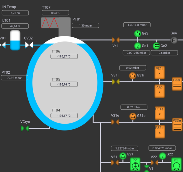
We went to EEroom to investigate the chiller, since we noticed that the CHILLER_PIPE_TE monitor suddenly increased a lot (see Fig. 1). Inside the chiller room, there was an allarm for one of the two chillers (the THERMOTEK chiller), so we filled it in with water (water flow was low) and swapped the filter that seemed a bit dirty, but it didn't restarted after this operation. After some trials we decided to use the spare chiller instead.
However, the OMI chiller wasn't working properly as well (linked to the DMS allarms) but we couldn't identify the problem. So, we decided to switch off everything for safety reasons for the weekend (Neovan amplifier and slave laser pump currents wer set to 0).
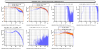
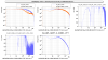
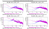
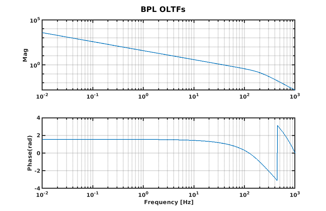
Profiting of the measurements made today, we extracted the plants of the four DoFs needed to design the control filters. The basic idea was to measure the several pole-zero structures in the mechanical plants, to compensate them in the control filters, in order to flatten the mechanical responses and have for all the four degrees of freedom the same open-loop with UGF at 40Hz, controlled by an integrator and a double pole to roll-off the transfer functions (see fig.1) (same as it was done for the BPC controls).
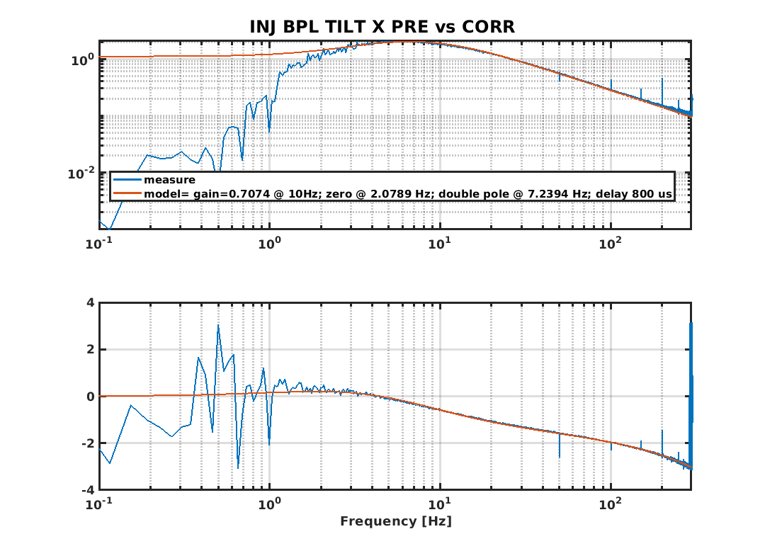
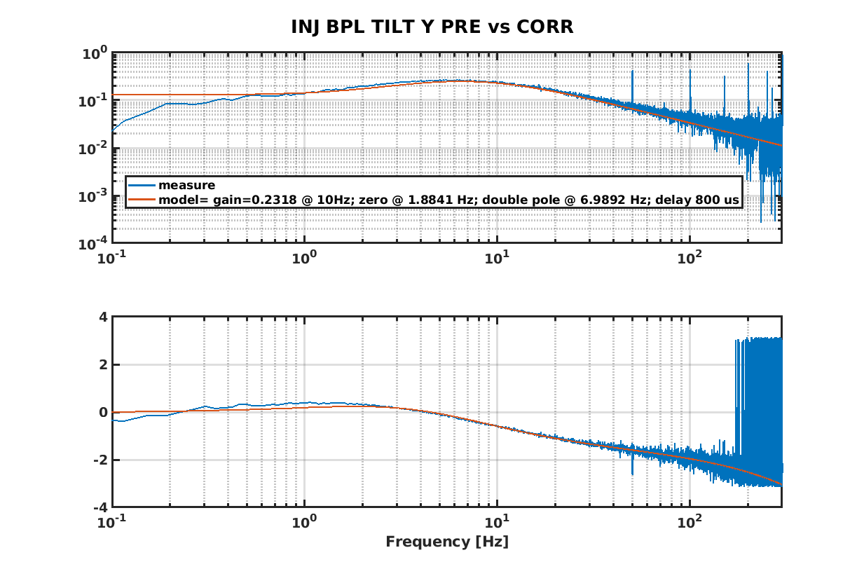
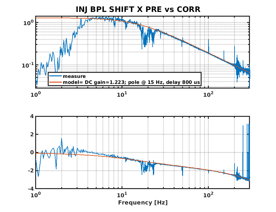
For future reference, the measured and fitted plants for tilt X/Y and shift X/Y are reported in fig.s 2,3,4 and 5, respectively.
The control filter to reduce the excess of noise visible on the TILT X dof spectra has been updated but will be tested next time.


Activities carried out during the day:
Noise injections on BPL loop carried out by INJ team
PR suspension control test
Switch-off of Neovan and slave lasers and chillers (flags shelved from today 17 LT until Monday) due to malfunctioning
Today EIB started to oscillate very heavily. We opened the controls but the bench didn't close anymore, because the TY started drifting. So, we went to laser lab to investigate the problem, and fixing a bit the position of the water tubes we found again a good position and the bench could be closed finally.
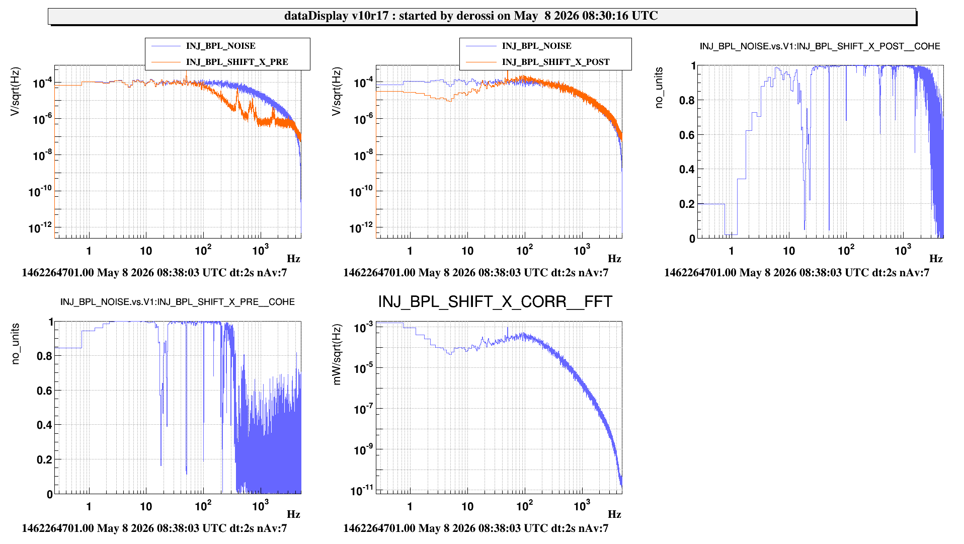
%%% noise injections on BPL %%%
We injected this noise BPL_noise_flt
ACL_FILTER_SET "BPL_noise_flt" 1 1 20 20
ACL_FILTER_ZEROS "BPL_noise_flt" 0.01 0
ACL_FILTER_POLES "BPL_noise_flt" 0.5 0
ACL_FILTER_POLES "BPL_noise_flt" 500 0.5
on the POST error signals. The error signals are filtered with the filter named BPL_PAOLO, which is taken from the BPC loop
ACL_FILTER_SET "BPL_PAOLO" 1 -3.3 10 20
ACL_FILTER_POLES "BPL_PAOLO" 0 0
ACL_FILTER_POLES "BPL_PAOLO" 200 0.7
ACL_FILTER_ZEROS "BPL_PAOLO" 10 0
The problem with this filter is that we are reintroducing noise at 10-100 Hz ( fig 2. in the entry made yesterday #69090), so the aim was to design a more adapted filter.
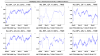
The GPS are the following (each duration is 3 min):
tilt x 08:14:00 UTC (fig. 1)
tilt y 08:20:40 UTC
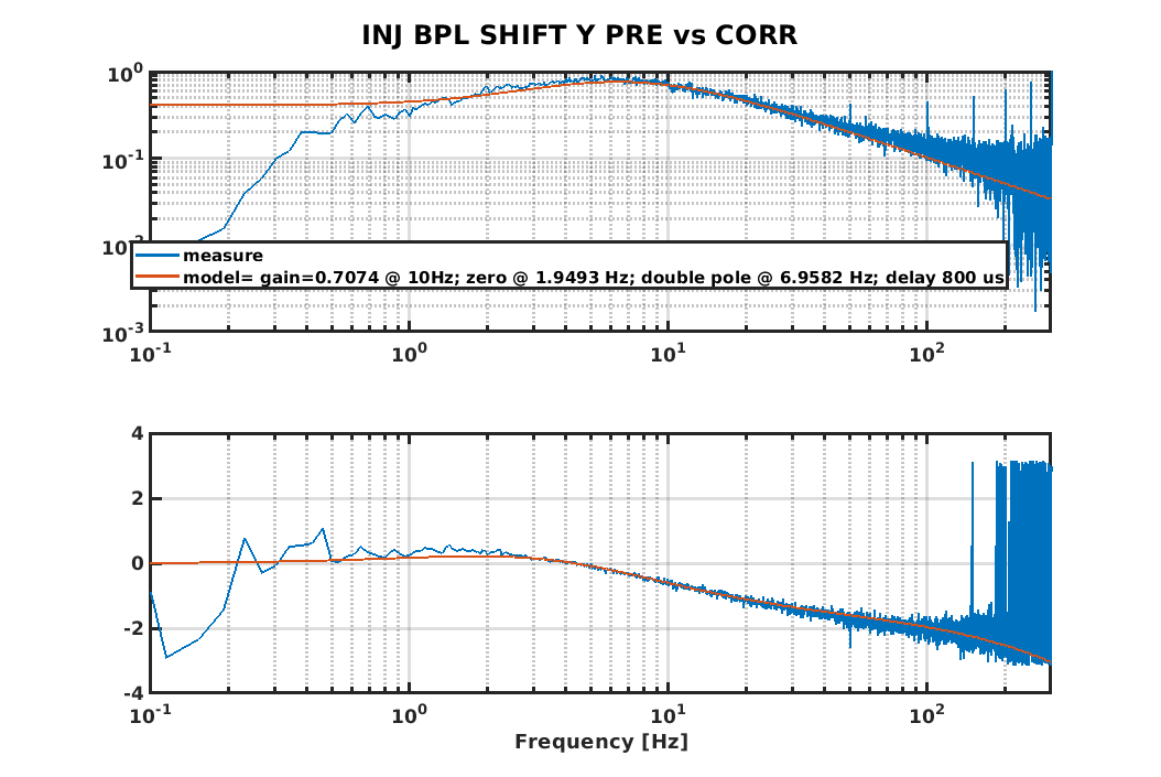
shift x 08:35:00 UTC (fig. 2)
shift y 08:42:00 UTC
The last plot shows the loop open and closed with the new filters designed by Manuel (in BPL filters: BPL_tiltx_flt, BPL_tility_flt, BPL_shiftx_flt, BPL_shifty_flt).
%%% clipping on the corrections %%%
The corrections sent to the DAC are now clipped -9.9 to +9.9 V (since yesterday we observed a misbehaviour of the PZT at 10V )
Updating the SBE server configurations for the DAC1955 V3 firmware, we fpund strange Tolm packet setting for some Acl*s servers running of the SQB1 rtpc, more precisely for
- the SQB1_LC server where the TOLM packets for the "SQB1_DAC_LC_LVDT_out_INT" and "SQB1_DAC_PSD" DAC1955 was not sent at the correct frequency
- TOLM_OUTPUT_PACKET_SLICED "SQB1_DAC_LC_LVDT_out_INT" 50000 DAC1955_FREQ with DAC1955_FREQ (= 100000)
- instead of TOLM_OUTPUT_PACKET_SLICED "SQB1_DAC_LC_LVDT_out_INT" 10000 DAC1955_FREQ meaning that only 2 over the 10 packets were sent
- same thing for TOLM_OUTPUT_PACKET_SLICED "SQB1_DAC_PSD" 50000 DAC1955_FREQ
We set the correct parameters but when we restarted the SQB1_LC server, we lost all the input Tolm packets . To recover the Tolm input packets, a reboot of the SQB1_rtpc was required .
We made several trials and at the end we set
- for the SQB1_LC server;
- this line for the SQB1_DAC_LC_LVDT_out_INT Tolm packet in order to have all the DAC sample: TOLM_OUTPUT_PACKET_SLICED "SQB1_DAC_LC_LVDT_out_INT" LC_LOOP_FREQ DAC1955_FREQ
- this line for the SQB1_DAC_PSD Tolm packet as the DAC channels are only constante value : TOLM_OUTPUT_PACKET_SLICED "SQB1_DAC_PSD" 50000 DAC1955_FREQ as previously
- for the SQB1_FI server, as we would like to have output Tolm data flow and it s only temperature control loops
- this line for the SQB1_DAC_01_INT Tolm packet : TOLM_OUTPUT_PACKET_SLICED "SQB1_DAC_01_INT" 50000 DAC1955_FREQ instead of TOLM_OUTPUT_PACKET_SLICED "SQB1_DAC_01_INT" LOOP_FREQ(10000) DAC1955_FREQ previously
With these configurations,
- all the servers are correctly running
- the output Tolm data flow is the same as before the modifications, meaning that the use of DAC1955 v3 firmware will be helpful
- the SBE and LC loops were successfully closed
Operations performed between 2026-05-07-13h45m08-UTC and 2026-05-07-14h47m25-UTC
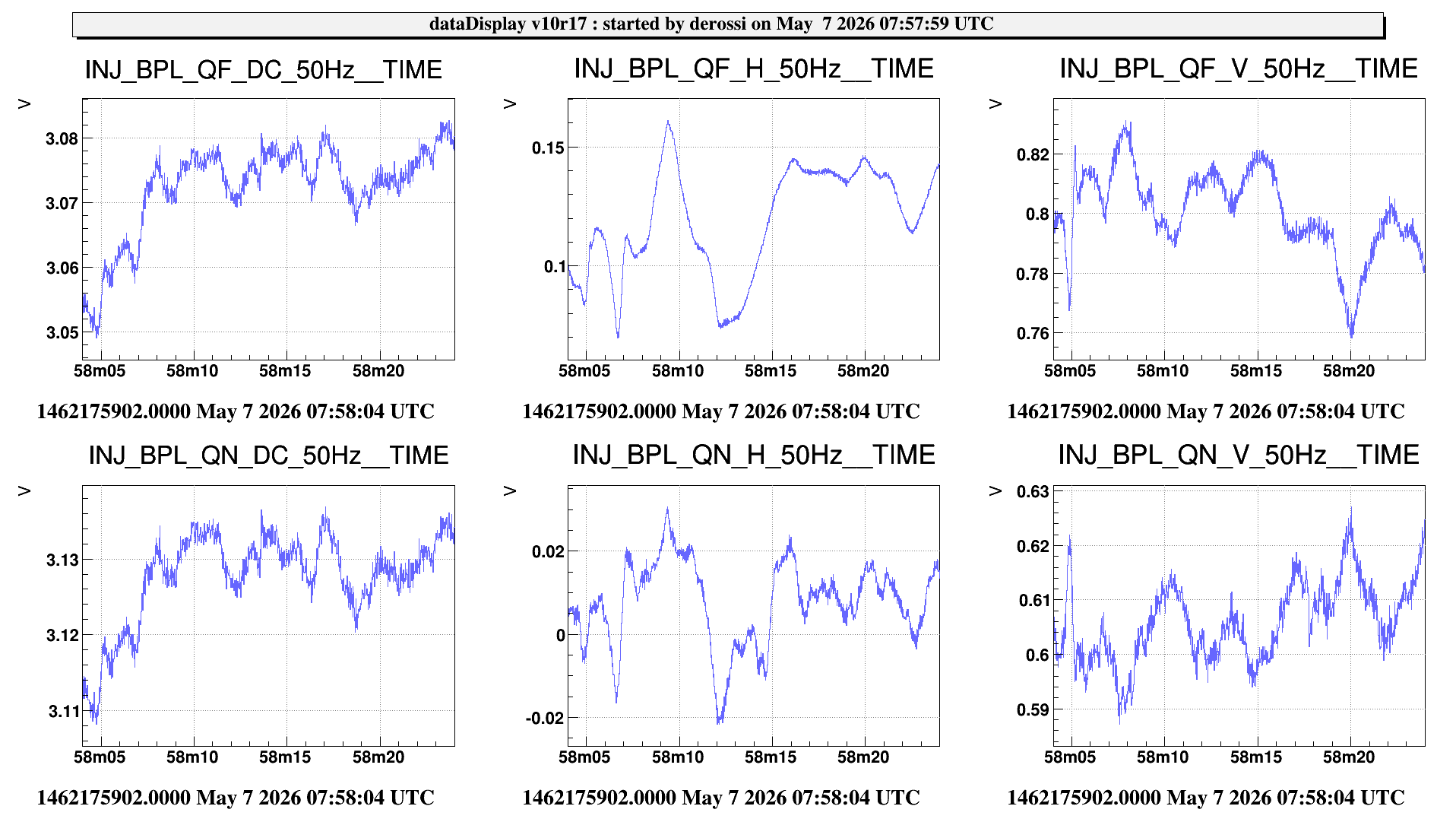
- This morning, before starting to work on the BPL loop, we unblocked the beam transmitted from the PMC and we took the references of its position on the BPL QPDs (see fig 1).
- Then we plugged the PZT to the DAC in Eeroom. The PZT driver accepts -2V +12V, while the DAC dynamics is +-10V but due to the LEMO 3 PIN - BNC adaptation it is restricted to +-5V. On the PZT driver the DAC input is summed with a offset (from 0 to 10 V) that can be manually adjusted, and then amplified by slightly more than a factor 10, to -30 +130 V. We manually set the offset to mid range (5V), so that we can correct around this value with the DAC.
lines 127-130 in /virgoData/VirgoOnline/ISYS_EER_dac.cfg
ACL_DAC_CH dac1955_EER_DAC2_ch03 1 DAC1955_FREQ BPL_PZT_EIB_M1BH_CORR 0 1 "None" "ad1955-10v" ""
ACL_DAC_CH dac1955_EER_DAC2_ch04 1 DAC1955_FREQ BPL_PZT_EIB_M1BV_CORR 0 1 "None" "ad1955-10v" ""
ACL_DAC_CH dac1955_EER_DAC2_ch05 1 DAC1955_FREQ BPL_PZT_LB_M14H_CORR 0 1 "None" "ad1955-10v" ""
ACL_DAC_CH dac1955_EER_DAC2_ch06 1 DAC1955_FREQ BPL_PZT_LB_M14V_CORR 0 1 "None" "ad1955-10v"
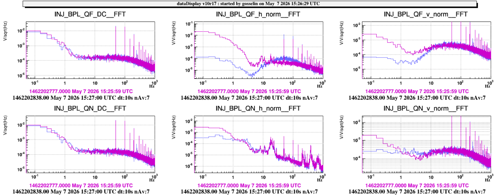
- We injected a 2Hz line on the PZTs during 90s. Here the gps for each actuator
gps = [1462194492 1462194603 1462194722 1462194871]; actuators = {'INJ_BPL_PZT_EIB_M1BH_CORR','INJ_BPL_PZT_EIB_M1BV_CORR', 'INJ_BPL_PZT_LB_M14H_CORR', 'INJ_BPL_PZT_LB_M14V_CORR'};
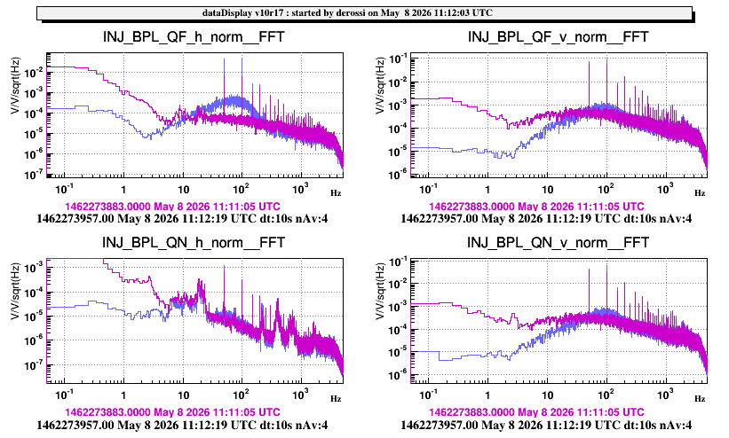
- The sensors are: {'INJ_BPL_QF_h_norm', 'INJ_BPL_QF_v_norm','INJ_BPL_QN_h_norm', 'INJ_BPL_QN_v_norm' };
- QF mainly see the tilt (done with EIB M1B and also a bit with LB M14)
- QN mainly see the shift (done with LB M14)
- We computed the driving matrix with the attached script and closed the loop. We started to try different filters (see 2nd plot). As a final test we removed the resistences at the output of the PZT driver, from around 15:58 UTC to 16:20 UTC (but there is a lot of noise on the signals, introduced by the amplifier itself, so we put it back).
To do next:
- to perform noise injections and design a better filter which does not introduce noise on QF h between 20 and 100 Hz
- check availability for a DAC +-20V
- add in the ISYS_BPL code:
- a latch to keep the setpoint when the loop is open
- clip on the corrections to avoid too large beam excursion
- trigger to open the loop if there is no signal

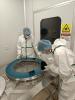
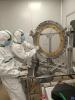
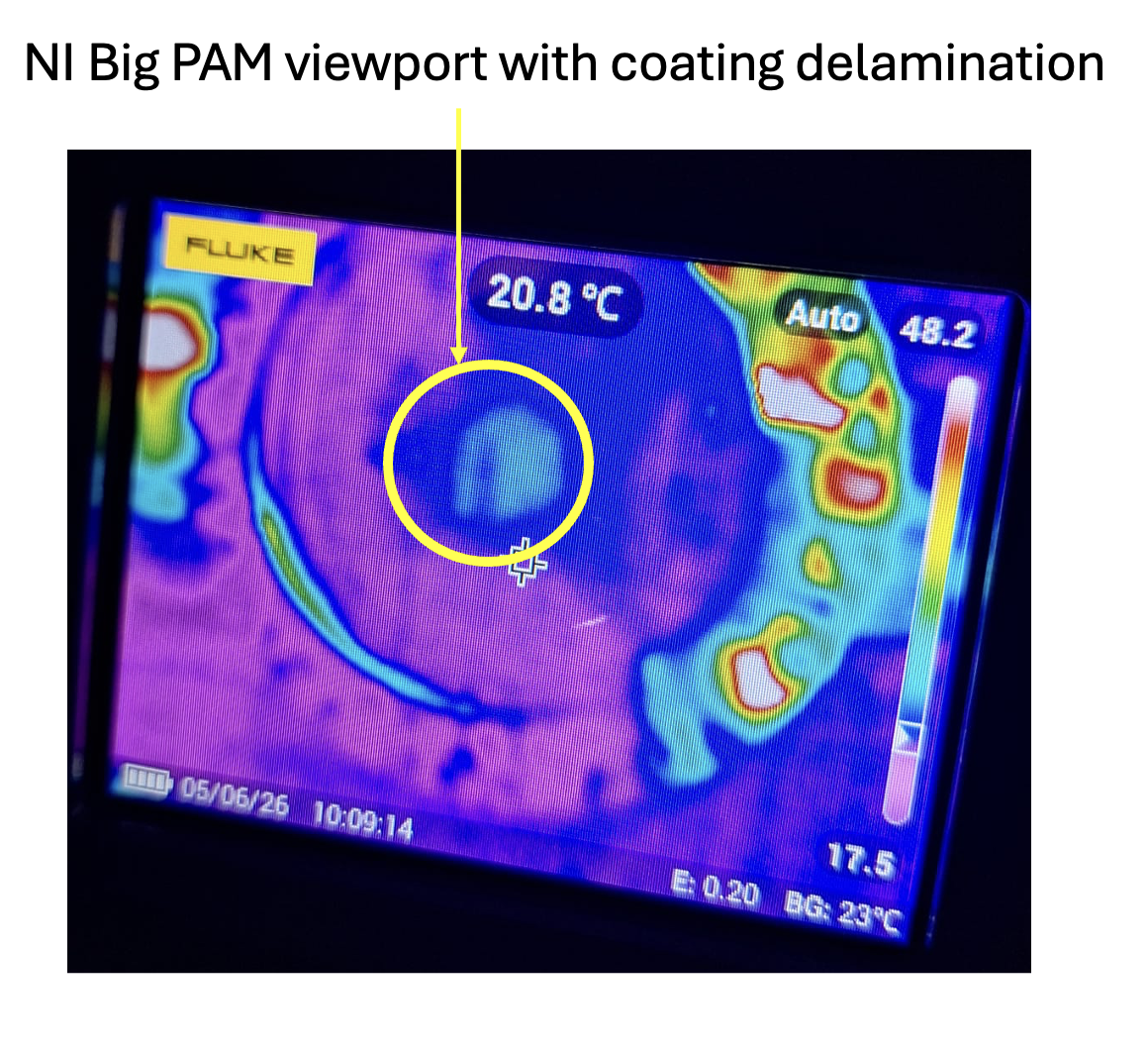
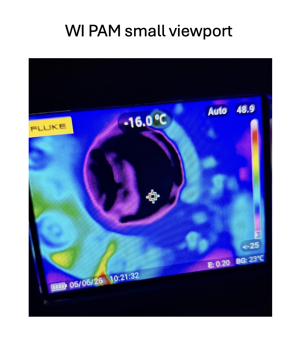
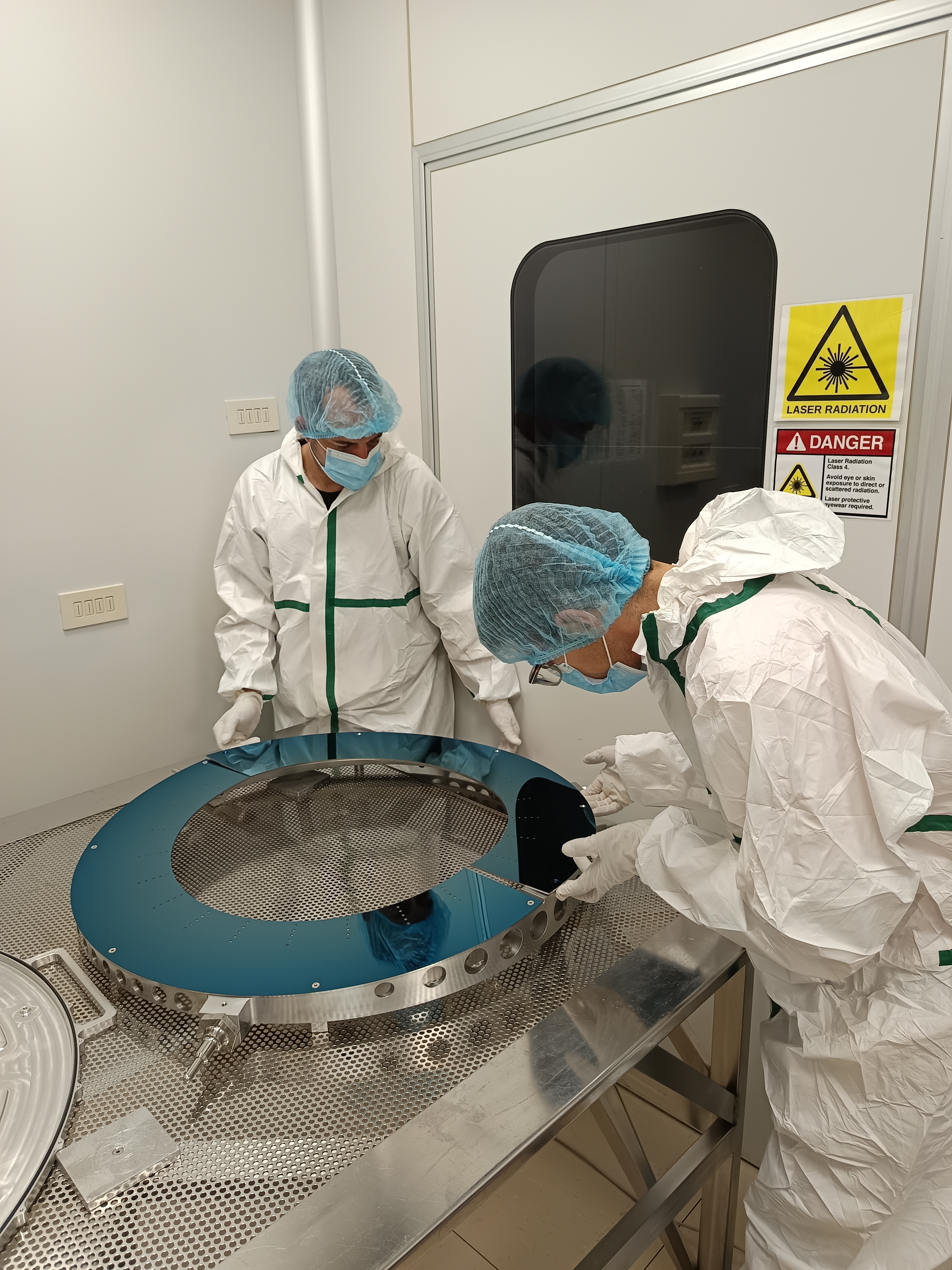
Yesterday, additional inspections (already reported in 69077) of the PAM viewports were carried out using a thermal camera:
- NI: big viewport — visible coating delamination (see Fig. 1)
- WI: small viewport — no visible coating delamination (inspected only from the outside see Fig. 2)


- PR suspension control test;
- BPL loop commissioning;
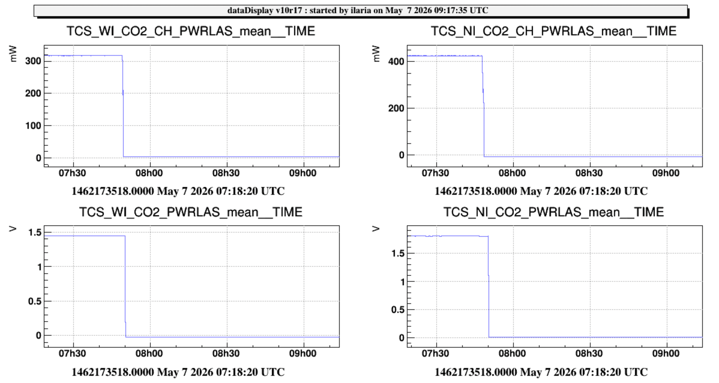
- CO2 lasers switch off (#69087);
- WI_MIR_PSDF local control glitches investigation (#69083);
the works on injection and suspension are still in progress...
At 07:50 UTC, all CO₂ lasers (CH and DAS) were switched off. Shortly thereafter, Cecilia deactivated the Guardian system and placed the chillers on standby.
Note: outputs disabled; power supplies left ON.
I went back and re-installed the ampifier I removed yesterday.
Data are back online (Fig.1), glitches still present.
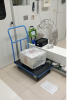
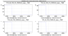
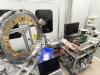
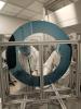
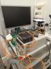
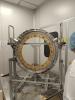
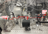
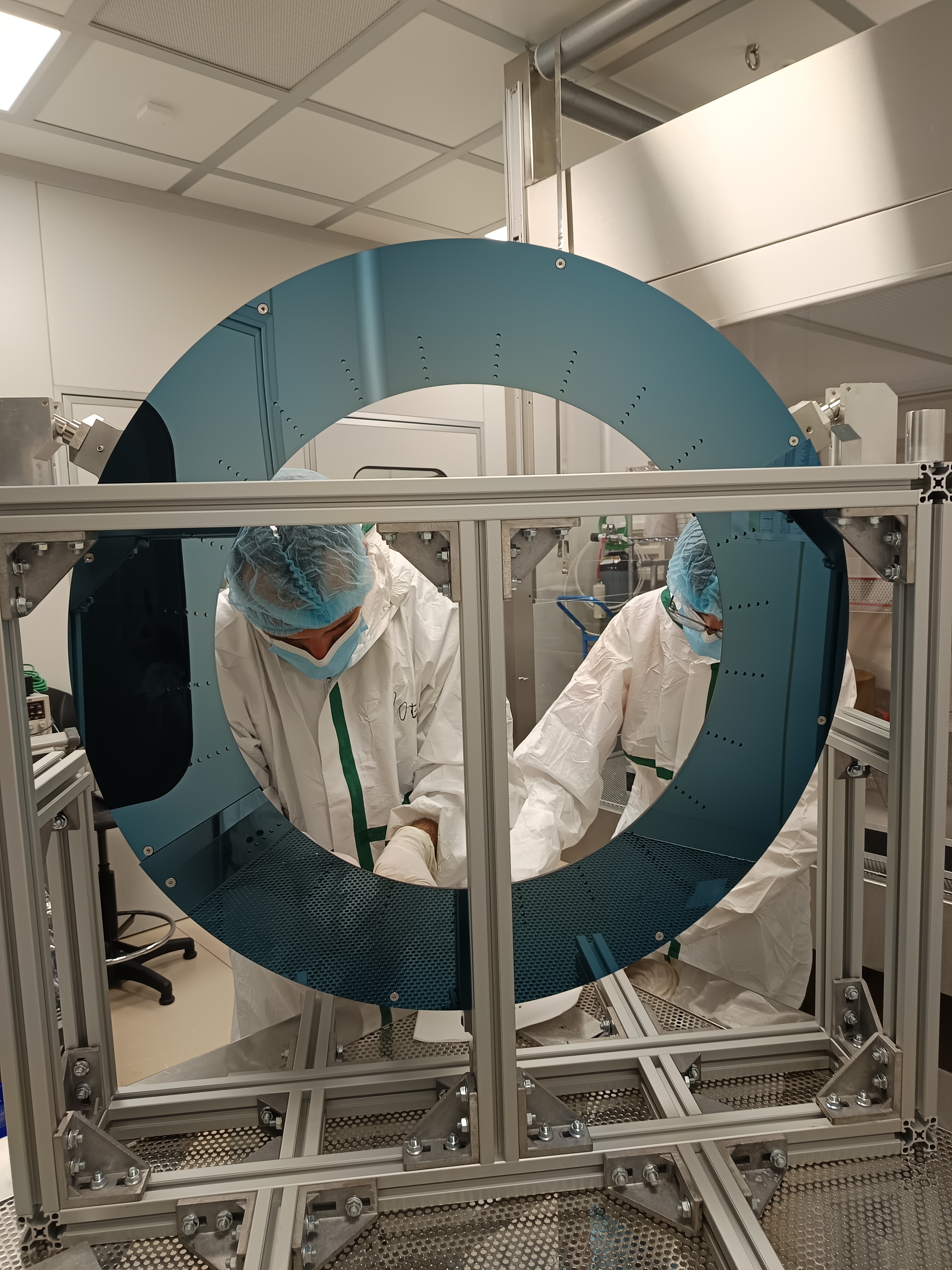
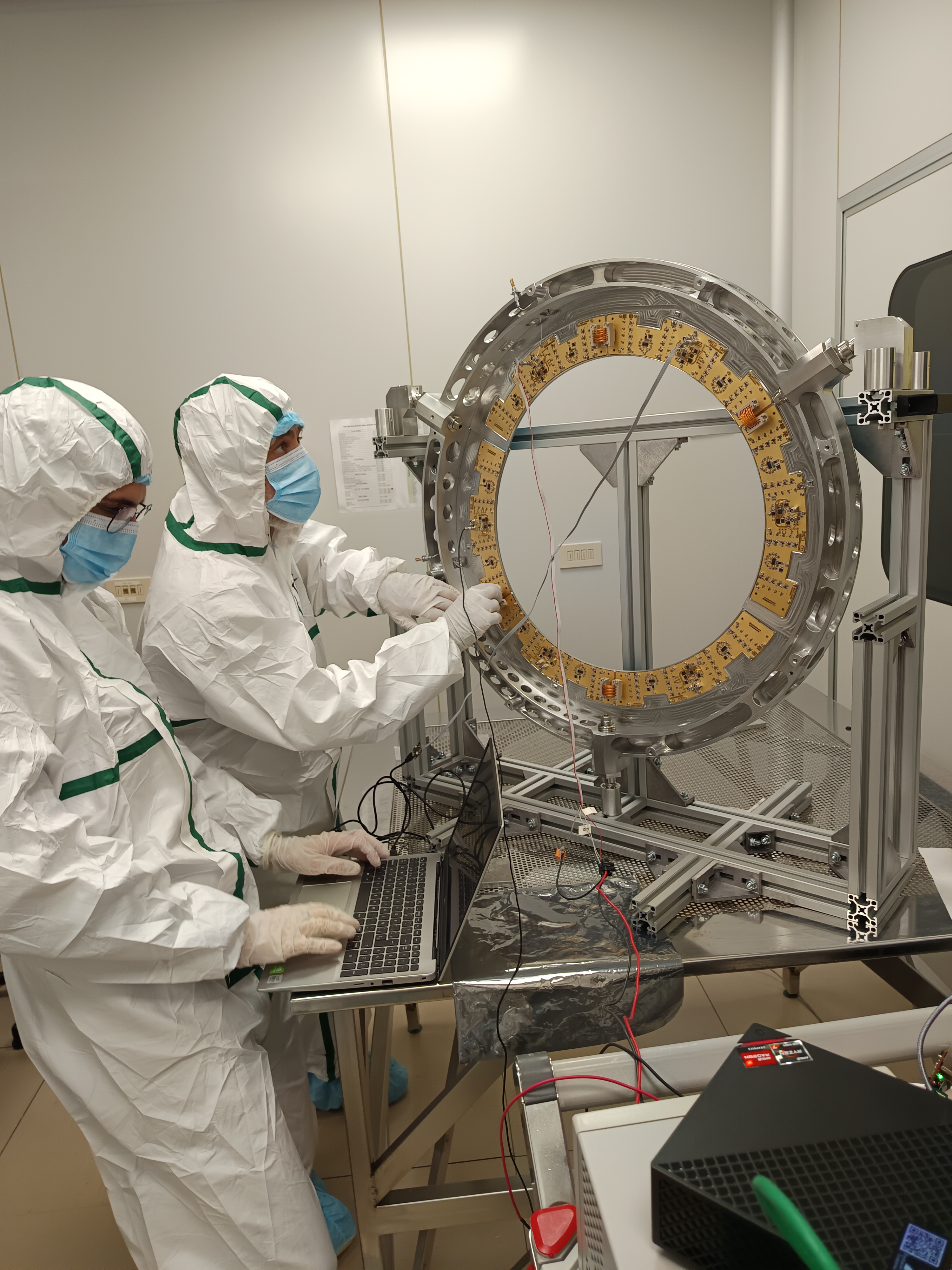
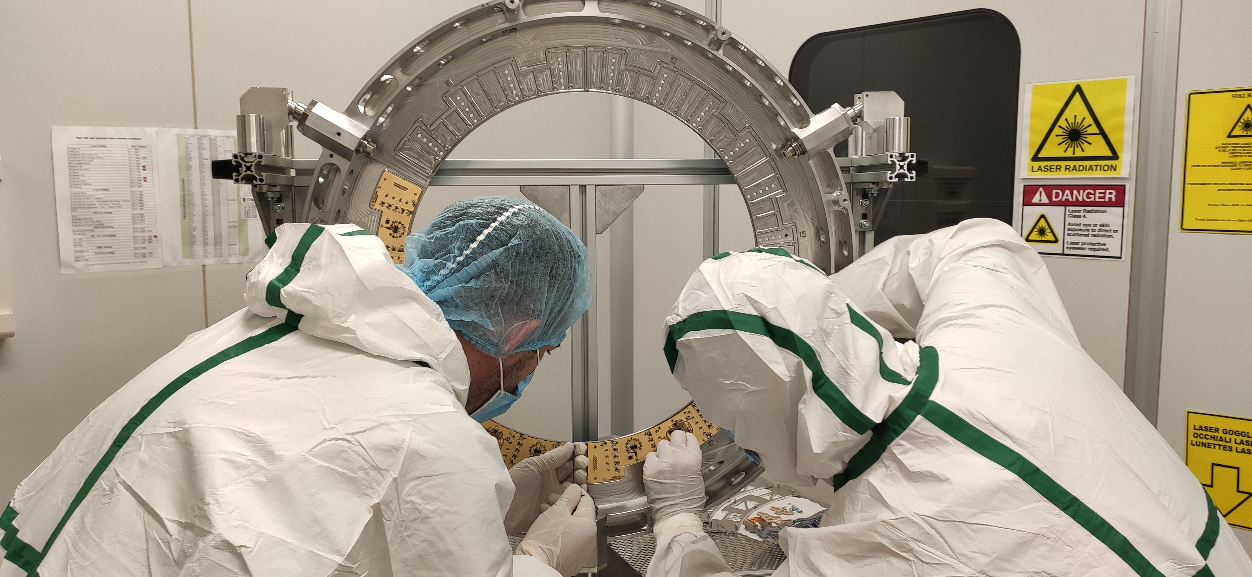
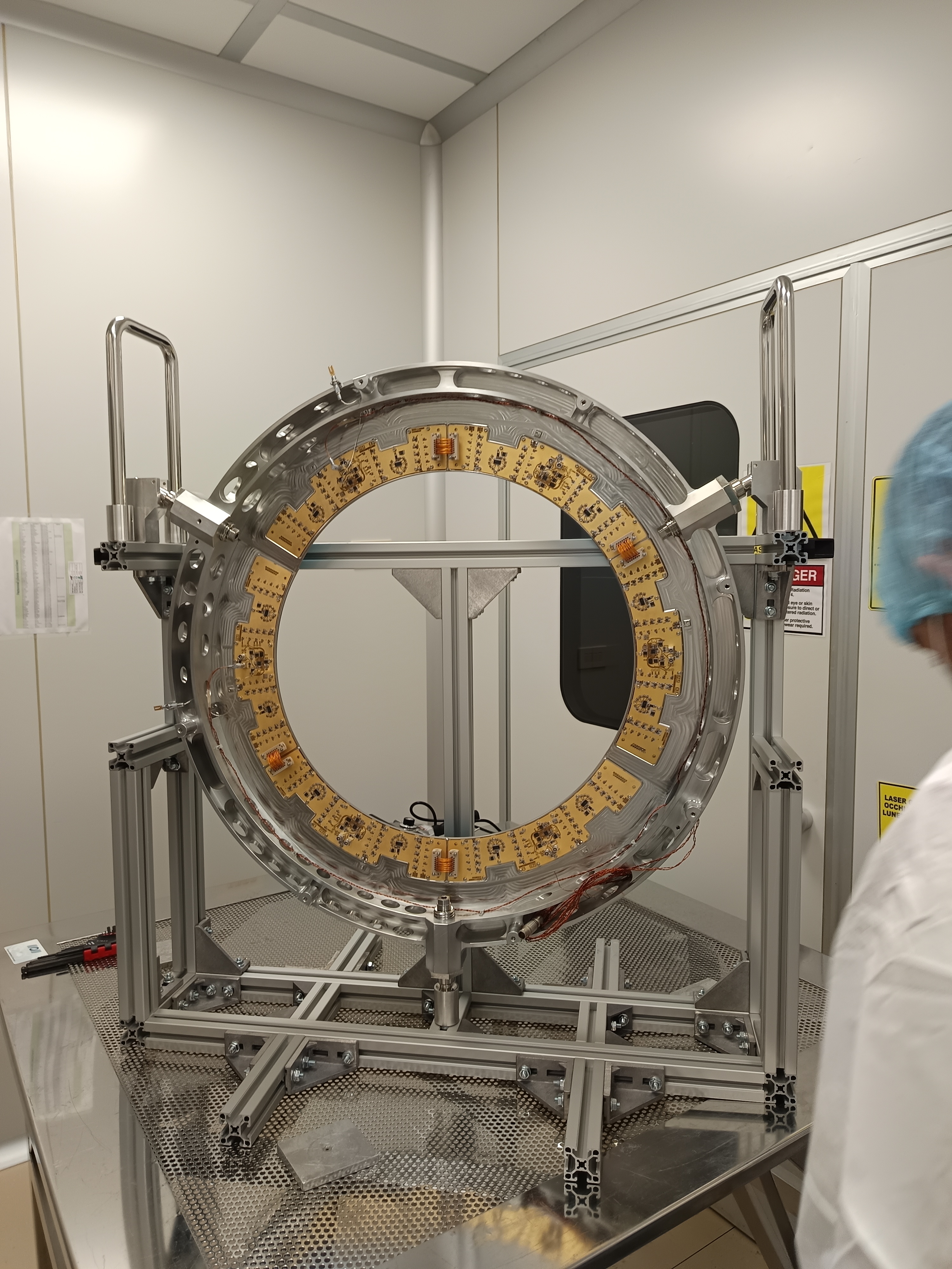
Once the mechanical part was completed and the PCBs assembled, we verified that the current in the two halves of the baffle was correct. The PCBs' impedance was checked separately and together, and the bias voltages were measured on each of them in the same way.
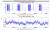
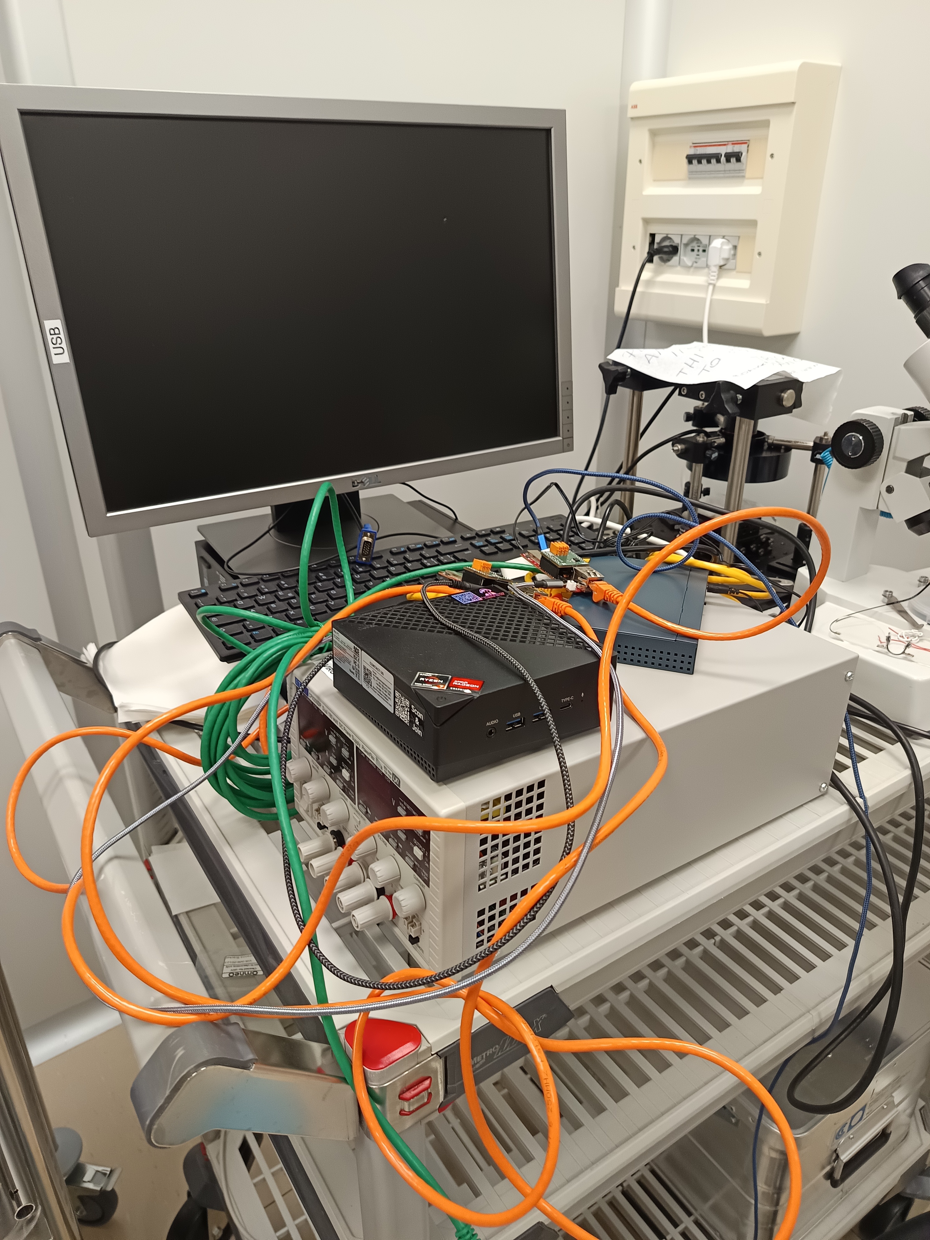
We acquired data first with the Wi-Fi antennas and the access point, and then with our RS485 cable, running each test for several minutes. We also read the temperature PT100 sensors and the voltage on the boards.
Once this was done, we tested the complete set of cables (a total of four, two for each instrumented baffle) provided by Vincenzo. After fixing a connector and a faulty cable the complete chain, including the feedthroughs, was tested.
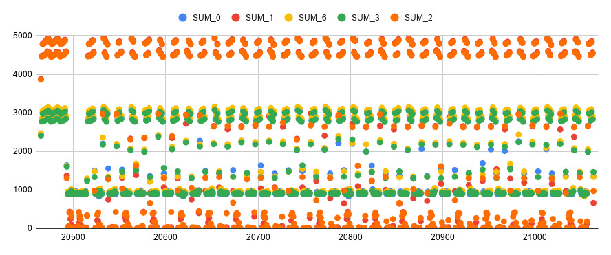
We have data from the last test set saved on the drive, which we will analyse. A preliminary graph of sums of ADC counts vs timestamp for few sensors is attached.
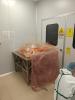
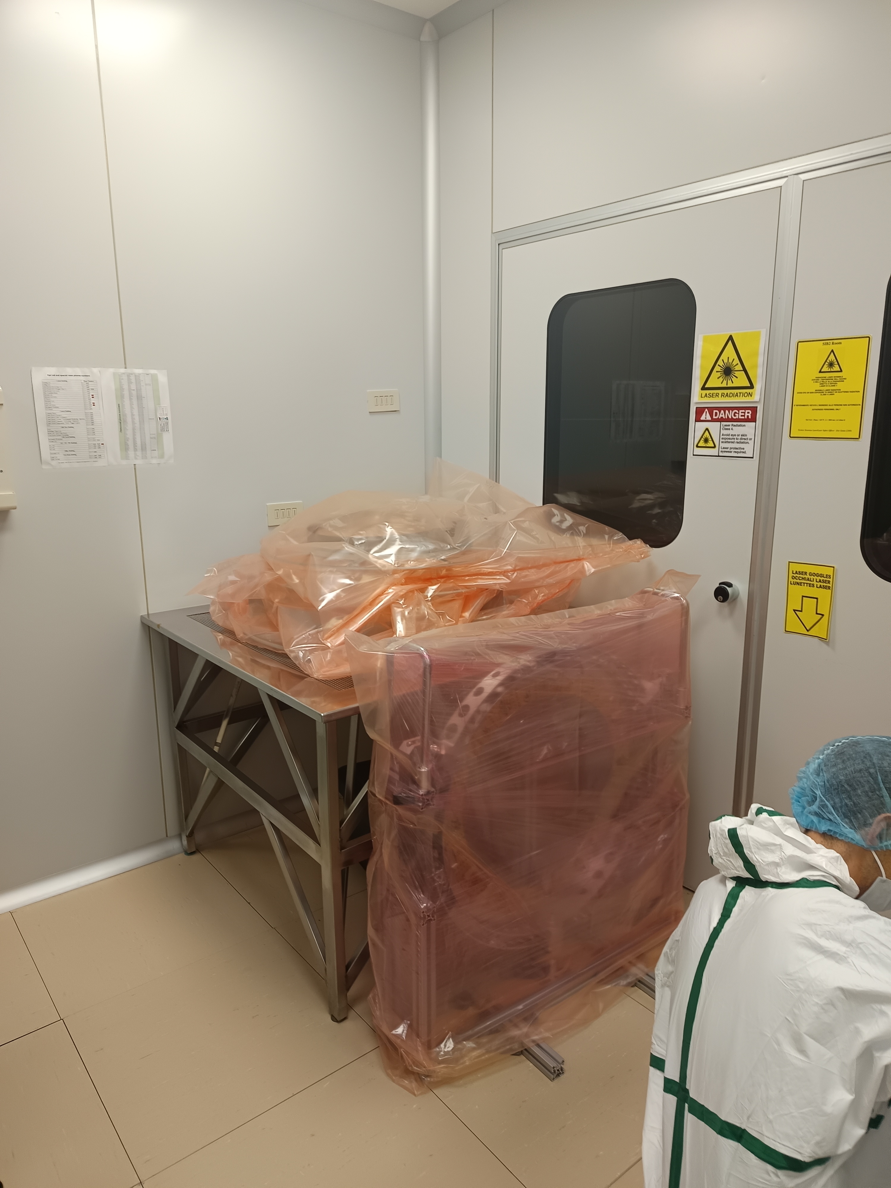
After the tests were concluded, the baffle was protected and left in the clean room ready for the assembly on Monday 11 May.

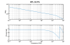
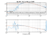
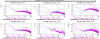
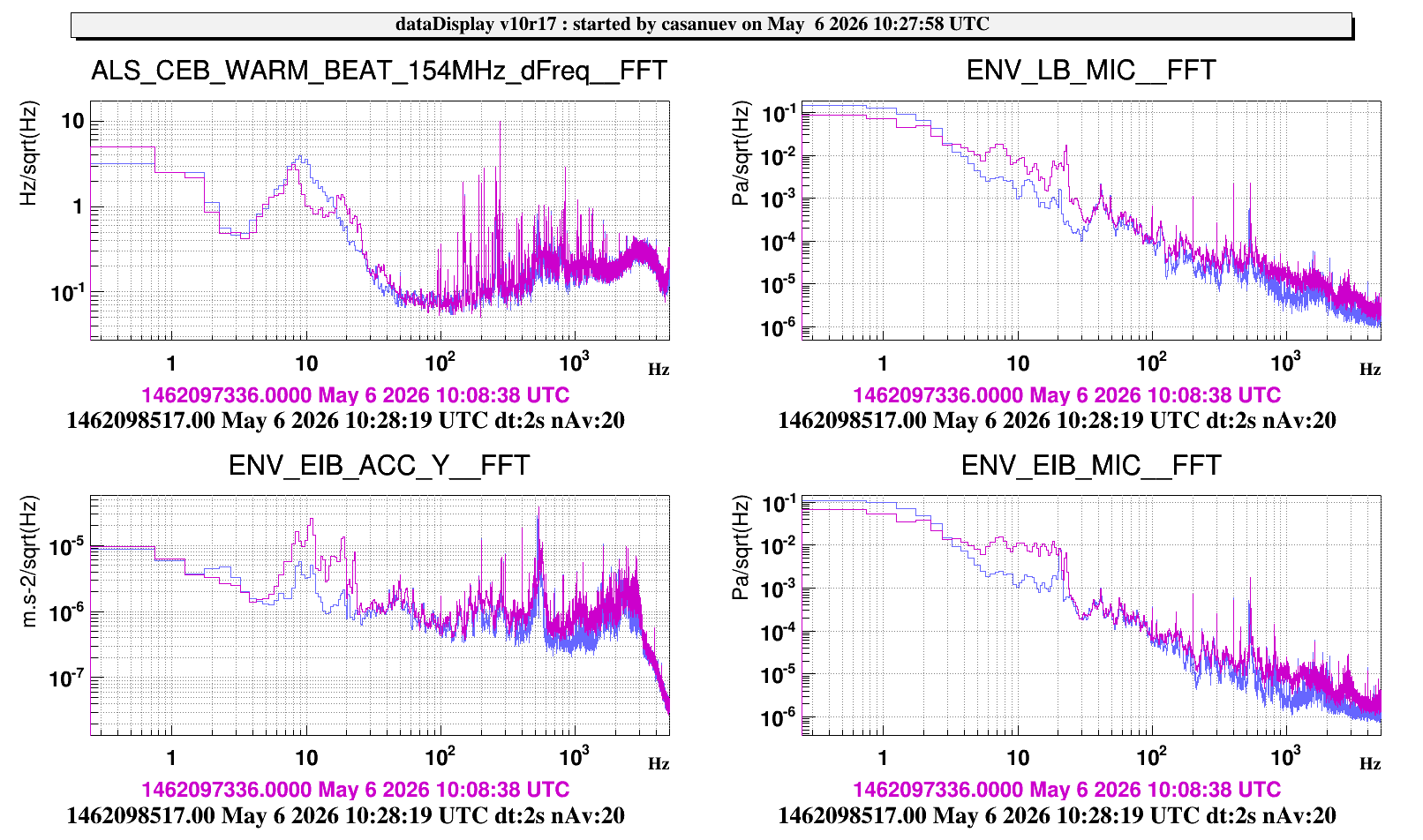
Yesterday morning we made a test turning off the air conditioning unit in the laser lab, in order to check if we are still dominated by the acoustic noise. In order to do this, we lock the west arm using the green beam and we checked the fft of the error signal with the air conditioning ON (purple curve) and OFF (blue curve). Figure 1 shows also different monitorings in the Laser and EIB bench (microphone and accelerometer).
In the plot the spectrum barely changes between the two states, which means that we are no longer dominated by the ambient noise which was the main target of this action. This will allow us to increase the bandwidth of the CARM and DARM loops (which currently are around 5 Hz), increasing the robustness of the system.

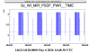
We investigated the missing signals on WI MIR local controls.
Spinicelli noticed that the SLD switch was off and flipped it, turning the beam back on. We realized that the contact between the power cord and the switch box is very precarious and turning or touching the cord is enough to turn the laser off again. We carefully adjusted its position until it worked, but it is clearly a non ideal situation and we will need to replace either the cable or the box itself.
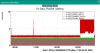
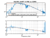
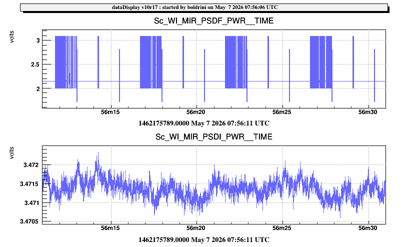
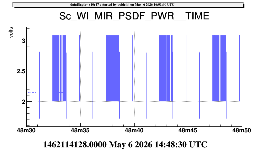
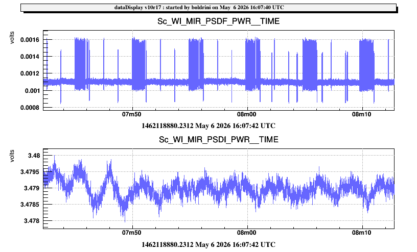
After turning the SLD back on, we noticed periodic glitches on WI_MIR_PSDF in the form of a ~1s long burst followed by two large glitches, spanning ~1 V peak to peak. This structure repeats every ~5 seconds (Fig.1).
We investigated this behavior by opening the local control box and swapping the cables between the amplifiers of the PSDF and PSDI photodiodes, both the power cables and the data cable connecting them to the photodiodes. The issue remained on PSDF, which led us to conclude that the amplifier itself was malfunctionig and we removed it to substitute its components.
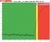
Surprisingly though, the PSDF signal still shows the same glitches without the amplifier (Fig.2), meaning that the issue is likely downstream, possibly at the level of dsp electronics. We will contact Boschi to investigate.
The current situation is that the signal is disabled, with the amplifier uninstalled and currently sitting in the Roma 1 office in the office building. We will reinstall the amplifier and restore the previous situation tomorrow morning, as the components inside the optical levers box are clearly not at fault for this issue.
Critically, the PSDF signal serves as reference for the WI's alignment and it must be restored in some form before uninstalling the mirror.
During the operations I had to move a magnetic field sensor out of the way to access the optical levers box. I repositioned it as precisely as I could and informed Tringali and Fiori afterwards.

I went back and re-installed the ampifier I removed yesterday.
Data are back online (Fig.1), glitches still present.
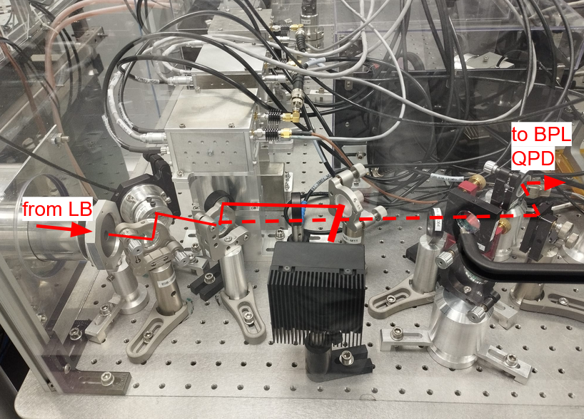
As a first step towards the commissioning of the BPL this afternoon we installed a mirror before the EOMs on EIB to send the main beam on a divergent lens (-30mm and then a beam dump), so that we will be safe while doing tests on the PZT (the risk would have been to burn something since the power density at the level of the EOMs is high).
We added 2 mirrors, 1 lens, 1 beam dump, and removed 1 iris, for a weight of about +1kg. We rebalanced the EIB and left it suspended. The PMC is scanning and the mirror at its output is flipped.
Tomorrow we will plug the PZT to the DACs and start the commissioning of the QPDs.
- This morning, before starting to work on the BPL loop, we unblocked the beam transmitted from the PMC and we took the references of its position on the BPL QPDs (see fig 1).
- Then we plugged the PZT to the DAC in Eeroom. The PZT driver accepts -2V +12V, while the DAC dynamics is +-10V but due to the LEMO 3 PIN - BNC adaptation it is restricted to +-5V. On the PZT driver the DAC input is summed with a offset (from 0 to 10 V) that can be manually adjusted, and then amplified by slightly more than a factor 10, to -30 +130 V. We manually set the offset to mid range (5V), so that we can correct around this value with the DAC.
lines 127-130 in /virgoData/VirgoOnline/ISYS_EER_dac.cfg
ACL_DAC_CH dac1955_EER_DAC2_ch03 1 DAC1955_FREQ BPL_PZT_EIB_M1BH_CORR 0 1 "None" "ad1955-10v" ""
ACL_DAC_CH dac1955_EER_DAC2_ch04 1 DAC1955_FREQ BPL_PZT_EIB_M1BV_CORR 0 1 "None" "ad1955-10v" ""
ACL_DAC_CH dac1955_EER_DAC2_ch05 1 DAC1955_FREQ BPL_PZT_LB_M14H_CORR 0 1 "None" "ad1955-10v" ""
ACL_DAC_CH dac1955_EER_DAC2_ch06 1 DAC1955_FREQ BPL_PZT_LB_M14V_CORR 0 1 "None" "ad1955-10v"
- We injected a 2Hz line on the PZTs during 90s. Here the gps for each actuator
gps = [1462194492 1462194603 1462194722 1462194871]; actuators = {'INJ_BPL_PZT_EIB_M1BH_CORR','INJ_BPL_PZT_EIB_M1BV_CORR', 'INJ_BPL_PZT_LB_M14H_CORR', 'INJ_BPL_PZT_LB_M14V_CORR'};
- The sensors are: {'INJ_BPL_QF_h_norm', 'INJ_BPL_QF_v_norm','INJ_BPL_QN_h_norm', 'INJ_BPL_QN_v_norm' };
- QF mainly see the tilt (done with EIB M1B and also a bit with LB M14)
- QN mainly see the shift (done with LB M14)
- We computed the driving matrix with the attached script and closed the loop. We started to try different filters (see 2nd plot). As a final test we removed the resistences at the output of the PZT driver, from around 15:58 UTC to 16:20 UTC (but there is a lot of noise on the signals, introduced by the amplifier itself, so we put it back).
To do next:
- to perform noise injections and design a better filter which does not introduce noise on QF h between 20 and 100 Hz
- check availability for a DAC +-20V
- add in the ISYS_BPL code:
- a latch to keep the setpoint when the loop is open
- clip on the corrections to avoid too large beam excursion
- trigger to open the loop if there is no signal
%%% noise injections on BPL %%%
We injected this noise BPL_noise_flt
ACL_FILTER_SET "BPL_noise_flt" 1 1 20 20
ACL_FILTER_ZEROS "BPL_noise_flt" 0.01 0
ACL_FILTER_POLES "BPL_noise_flt" 0.5 0
ACL_FILTER_POLES "BPL_noise_flt" 500 0.5
on the POST error signals. The error signals are filtered with the filter named BPL_PAOLO, which is taken from the BPC loop
ACL_FILTER_SET "BPL_PAOLO" 1 -3.3 10 20
ACL_FILTER_POLES "BPL_PAOLO" 0 0
ACL_FILTER_POLES "BPL_PAOLO" 200 0.7
ACL_FILTER_ZEROS "BPL_PAOLO" 10 0
The problem with this filter is that we are reintroducing noise at 10-100 Hz ( fig 2. in the entry made yesterday #69090), so the aim was to design a more adapted filter.
The GPS are the following (each duration is 3 min):
tilt x 08:14:00 UTC (fig. 1)
tilt y 08:20:40 UTC
shift x 08:35:00 UTC (fig. 2)
shift y 08:42:00 UTC
The last plot shows the loop open and closed with the new filters designed by Manuel (in BPL filters: BPL_tiltx_flt, BPL_tility_flt, BPL_shiftx_flt, BPL_shifty_flt).
%%% clipping on the corrections %%%
The corrections sent to the DAC are now clipped -9.9 to +9.9 V (since yesterday we observed a misbehaviour of the PZT at 10V )
Profiting of the measurements made today, we extracted the plants of the four DoFs needed to design the control filters. The basic idea was to measure the several pole-zero structures in the mechanical plants, to compensate them in the control filters, in order to flatten the mechanical responses and have for all the four degrees of freedom the same open-loop with UGF at 40Hz, controlled by an integrator and a double pole to roll-off the transfer functions (see fig.1) (same as it was done for the BPC controls).
For future reference, the measured and fitted plants for tilt X/Y and shift X/Y are reported in fig.s 2,3,4 and 5, respectively.
The control filter to reduce the excess of noise visible on the TILT X dof spectra has been updated but will be tested next time.
- DMS WEB infrasctructure upgrade (#69080);
- laser lab hvac switch off test;
- PR suspension control test;
- NI tower baffles removal;
- LB-EIB pointing control loop commissioning;
the works inside the laser lab and on PR suspension are still in progress...
This morning, we upgraded the machine hosting both the database and the web component of the DMS service.
The procedure was carried out as follows:
- The servers were stopped to prevent any further database writes.
- The database was copied to the test environment, where the application code had already been verified and updated in preparation for the upgrade.
- The old production machine was powered off, and the test machine was cloned and renamed using the original production hostname.
- The new machine was moved to the same Pool as the previous production system.
- The new machine was activated.
- Both backend services and the web interface were verified to be fully operational.
New system configuration:
- Server: AlmaLinux 9
- Web Server: Apache 2.4 (php-fpm)
- PHP: 8.3.30
- Database: MariaDB 10.5.29
- phpMyAdmin: 5.2.3
The entire process took approximately 2.5 hours, from 09:00 LT to 11:30 LT, during which the DMS service was unavailable. Most of the time was spent copying the database, particularly the tables containing plot data.
The application code had been previously tested in the environment. No anomalies have been detected so far; however, the system will continue to be monitored over the coming days.