* OMC 56MHz filtering with good ITF alignment do not appear limited by OMC1 astigmatism
We have been blaming the issues with 56MHz RIN on the astigmatism of the spare OMC that replaced the damaged OMC1.
Looking the data with injected 56MHz RIN lines this might not be entirely true.
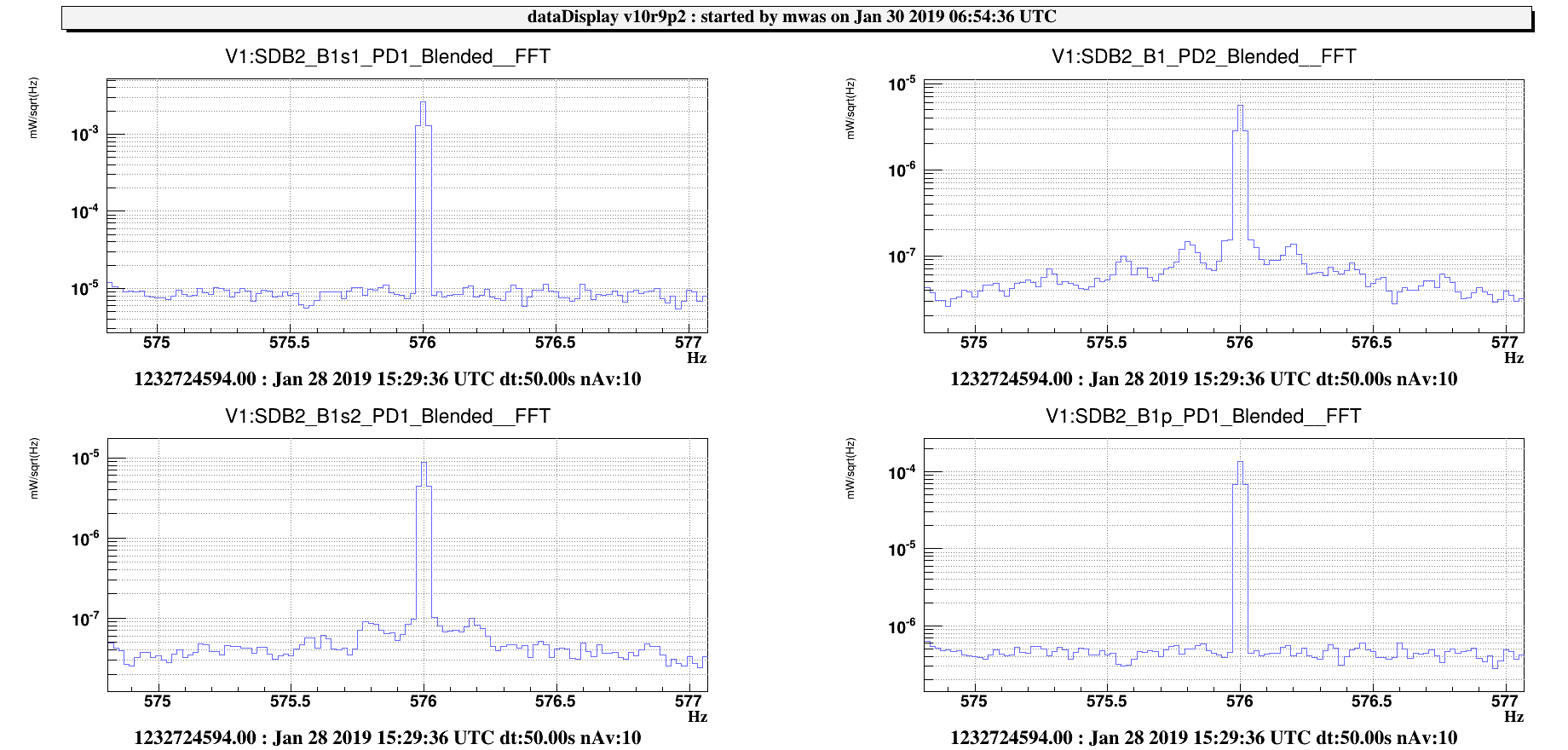
Figure 1 shows spectra during the injection of line at 576Hz into the 56MHz RIN.
On B1s1 the line has a height of 2.5e-3, and on 1.5e-4. B1s1 sees 10% of the power and B1p_PD1 sees 0.5%, so in both cases the line height for the total power is ~3e-2.
On B1s2 we see the lighted transmitted by OMC1 and rejected by OMC2, the line height there is 1e-5, but the B1s2_PD1 sees only 8% of the power, so this corresponds to a height of 1.3e-4 on the total power.
This means that the 56MHz attenuation by OMC1 is 1.3e-4/3e-2 = 4.3e-3 (reduction by a factor 230). In theory for a perfect OMC we expect a reduction by a factor 250 for the 56MHz TEM00. So OMC1 is actually filtering the 56MHz as expected.
On B1_PD2 we see a line height of 5e-6, and B1_PD2 sees at the moment the total power, so the 56MHz attenuation by OMC2 is 5e-6/1.3e-4 = 3.8e-2 (reduction by a factor 26). The filtering is 10 times worse than for OMC1! This is surprising.
One thing to note is that the filtering of one OMC for the 56MHz TEM10 is expected to be by a factor 25. So an explanation could be that 56MHz at the output of OMC1 has a TEM10 shape, so it couples more easily through OMC2.
Another piece of evidence showing that OMC astigmatism is not a limitation for 56MHz filtering. Is that the bump at ~900Hz has been shown to be due to 56MHz RIN. And that bump present below the PD shot noise has already been there at a similar height in June 2018 before the OMC replacement
In conclusion, when the ITF alignment is good the OMC1 56MHz filtering is nominal. So we should not assume that replacing the OMC by a non-astigmatic one will solve the 56MHz contamination issue. However, having a non-astigmatic OMC1 will still make the 56MHz filtering less critically dependent on alignment.
One thing to check would be to scan OMC1 without a DARM offset to see the order 1 mode of the upper and lower 56Mhz side-band. This should help characterizing how much 56Mhz TEM10 is really getting through OMC1. Locking the OMC on the 56MHz TEM10 mode, and trying to minimize that mode through ITF alignment set points, could be a figure of merit for carrier vs 56MHz relative alignment. However the 56MHz RIN is not a significant issue at 52Mpc when the ITF is well aligned by usual means, so this may not be that useful.