Reports 1-1 of 1 Clear search Modify search
AdV-ALS (Green sources)
derossi, spinicelli, melo, lagabbe, gosselin - 20:03 Tuesday 21 April 2026 (69019) Print this report
Free space beating installation

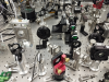
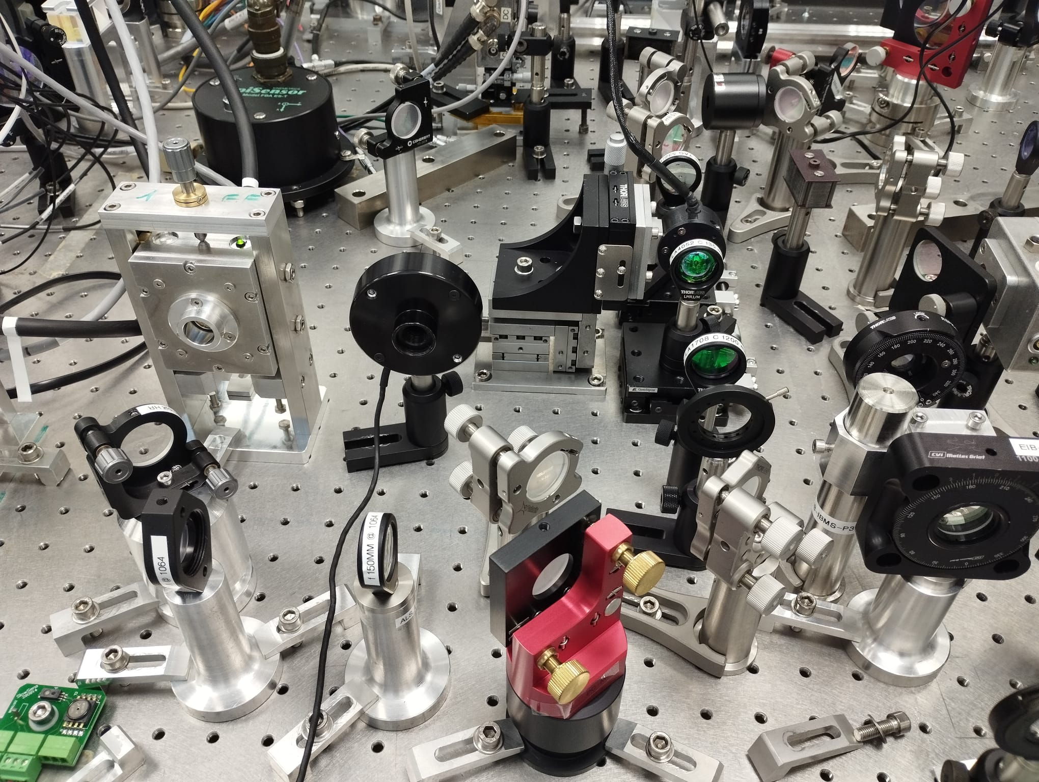
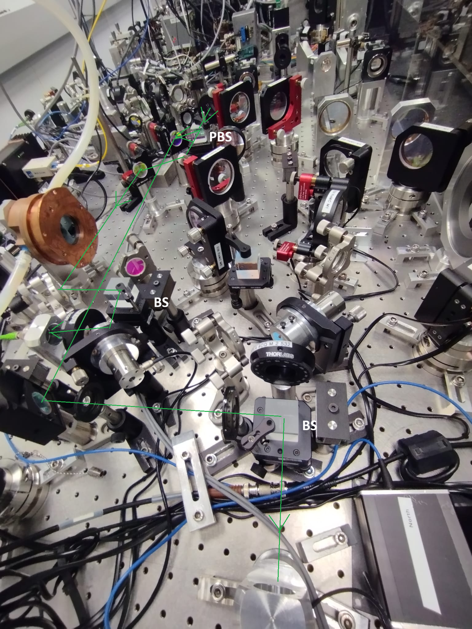
Today we could start to work on the ALS line on the EIB. A sketch of the pick off is shown in fig.1.

69019_1776780529_ALSpickoffonEIB_sketch.png

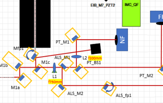
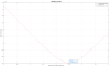
We started by characterizing the beam at the input of the EIB.
Since there are 45W coming from the LB, we could only analyze the beam after M1c, which is a beam splitter 97/3 made from the LMA (the characterization of the mirrorgives  made by the LMA gives transmittivity of 2.7% at 45°  polar S. The AR coating on the second surface has a reflectivity of 260 ppm). We added another BS 97/3 in order to further attenuate the beam for the beam scan.
%beam at the input of EIB
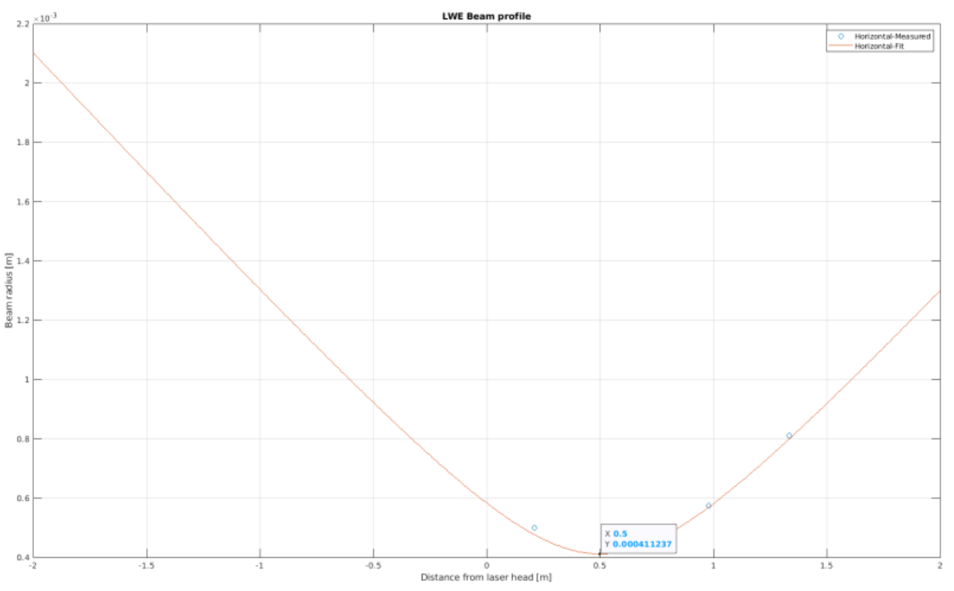
Z=[54 95.5 124 175]*1e-2; %beam at the input of EIB
Wx=[1367 1516 1706 2144]*1e-6*0.5; Wy=[1370 1511 1685 2055]*1e-6*0.5;
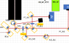
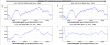
The waist position is z0 = 13 cm from the EIB border, and its value w0 = 638 um. (fig.2 )

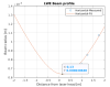
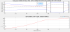
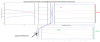
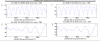
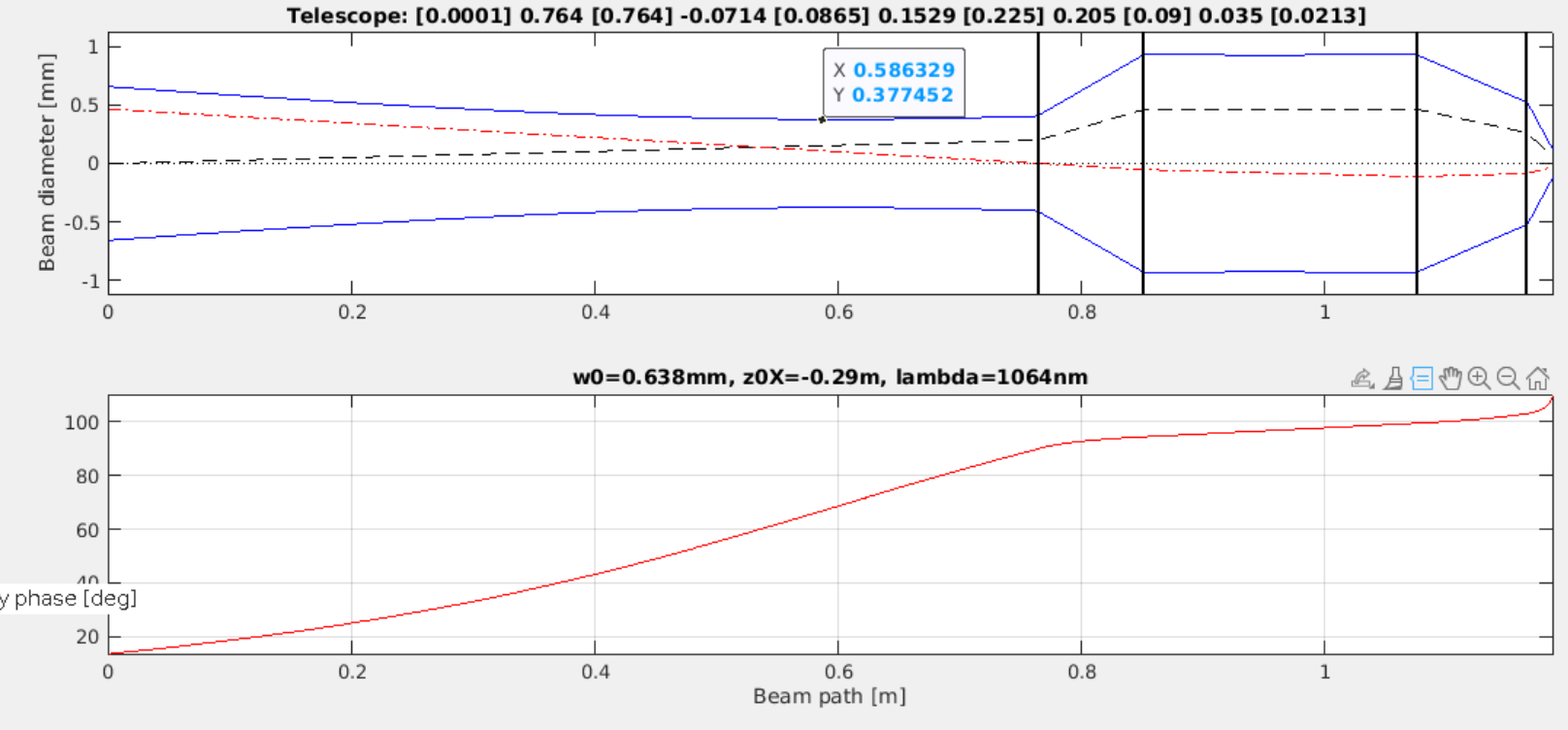
This is quite consistent with the values taken from the optocad (on which Matthieu based the telescope, shown in fig 3). Since the telescope is designed positioning L1 29cm away from the waist of the beam which is 638 um, we positioned L1 13 cm + 29 cm from the EIB border. We characterized it (shown in fig 4):
%beam after L1
Z=[54 95.5 124 175]*1e-2; %beam after L1
Wx=[1001 855 1147 1622]*1e-6*0.5; Wy=[999 900 1167 1562]*1e-6*0.5; 

We installed after 75cm from L1 the diverging -70mm lens and the 150mm lens, spaced by around 8.6cm (verifying after these two that we have the good waist with the beam scan).


Images attached to this report
Comments to this report:
derossi, spinicelli, gosselin, lagabbe, melo - 20:09 Wednesday 22 April 2026 (69024) Print this report

Today we installed the telescope to focalize into the PPLN crystal (waist in the crystal 17um). See first 2 attached photos.

The last lens f=75 mm is positioned at around 110mm from the one before the crystal of f=35mm and is needed to collimate the beam.

We obtained an IR beam with 3.1 mm diameter, collimated over 80cm. For the green beam we will have a diameter of 1.8 mm (see pict 3. On the bottom is the propoagation of the green beam after the waist in the crystal, while on the top is the whole telescope for the IR).

The telescope has been designed to inject the green beam in the fiber coupler Thorlabs PAF2A11A (MFD 1.8mm). So it is not very well adapted to inject the IR in the coupler PAFX11C (MFD 2.09mm), and we will have to add a lens with a focal of 1000mm to have the good size of the beam at the level of the coupler.

After optimization of the alignment and the temperature of the crystal oven (set to 113,27C) we obtained 27,4 mW of green over 1.19 W of IR, which is a conversion efficiency of 1.9% (as expected).


Images attached to this comment
derossi, gherardini, gosselin, lagabbe, spinicelli - 20:55 Thursday 23 April 2026 (69030) Print this report

Today we completed the alignment of the setup for the CEB green beam generation (previously installed into the Atrium). The green beam is now generated with the expected efficiency, the IR and Green monitoring photodiodes have been installed, connected to the DAQ and aligned (fine tuning will be performed once the EIB is re-balanced and suspended), flip mirror and picomotors have been installed. Moreover, the IR pickoff for SNEB/SWEB is now injected into the fiber ( ~70% coupling).

In the afternoon, we began aligning the green beam towards the PBS where the two arm green beams separate, by counter-propagate an external green laser. We installed two diaphragms as reference points and started the coarse alignment.

Tomorrow we will attempt to inject the reference beam into the two fiber couplers that will be connected to the fiber beating photodiodes.

spinicelli, lagabbe, nenci, melo, cavalieri - 15:14 Monday 27 April 2026 (69035) Print this report

##entry of last Friday lost in the drafts##

We continued the alignment of the green beam towards the North/West fiber couplers. We were able to follow the path of the counter-propagated green laser and finally reach both fiber couplers.

After several attempts, we successfully injected the reference beam into one of the two fibers (the one corresponding to the North Arm) with ~30% coupling efficiency. Unfortunately, on the other fiber we could only achieve ~0.5% coupling (without further touching the alignment). This suggests that the axes of the beams coming from the two arms are not perfectly superimposed.

However, a fine adjustment will be carried out on Monday using the two mirrors equipped with picomotors (see Fig. 1).

Side note: 

  • We temporary connected the picomotors of the two ALS mirrors (used to align the reference beam) to the "picoAppEIB" server. For the time being,  the first mirorr (bottom circle on fig. 1) is controlled using "FAR_M1_{Tx, Ty}" DoF, the second one (top circle on fig. 1) using "M8_{Tx,Ty}". 
  • We added the control of the flip mirror for the reference green beam (violet circle on fig. 1). It is now connected to the TTL_inj server in the flip mirror TCS rack of the piscina, on the channel 5 (green cable in fig. 2).
  • In addition, we also prepared two additional flip mirror cables (yellow and blu ones),  which may be used in the future on the main beam path.
Images attached to this comment
derossi, spinicelli, melo, lagabbe - 19:36 Monday 27 April 2026 (69041) Print this report
  • We decided to create two different paths to independently align the two reference beams into the N and W RF photodiodes (see photo). We did not touch the optics for the beams coming from the arms in order to keep the reference. The beating will be aligned once we will have the green from the ends.

          The size of the beam at the level of the collimators was 1500 um instead of the 1800 um required for the coupler Thorlabs PAF2A 11 A, so we adjusted the lens after the crystal to get the right beam size.

           We got:

                  -  1 mw /1.3 mW for the north --> 77% coupling efficiency

                  -  180/220 uw for the west --> 80% coupling efficiency

           Then we tuned the waveplate to have the same power on the two paths --> 740 uW on each 

  •  From the main ALS pickoff at the beginning of the EIB we get max 1.15W of IR power, which is converted into the crystal to 27.5 mW green --> 2% coupling efficiency
  • The IR pickoff to the DAQ room has been optimized again (since we moved the lens after the crystal): 270 mW/400 mW in the IR pickoff --> 67% coupling efficiency. The fiber has been connected and we send 35mW of IR to the DAQ room box (to be split and sent to WEB and NEB). This was the same value as before (chosen since more power would induce Brillouin scattering).
Images attached to this comment
derossi, melo, lagabbe - 12:07 Tuesday 28 April 2026 (69042) Print this report

This morning we finished the work on EIB for the ALS part. The next step will be to commission the beating once we will have the green from the arms.

  • We calibrated the monitor photodiodes and connected to the ADC the RF photodiodes. The IR pickoff is around 1,16 W and 26 mW of green beam are produced  (1st attached plot).
  • The IR pickof arrives to the end buildings and the green is produced (plot 3).
  • The total added weight for the ALS part is around 19kg. In the attached pdf there is the list of the installed optics. To be considered that 21.1 kg had been removed at the beginning of the installation (IBMS setup, not used anymore).
Images attached to this comment
Non-image files attached to this comment
Search Help
×

Warning

Error

The present report has been modified outside this window. Please check for its integrity in the main page.

Refreshing this page will move this report into drafts.

×