Reports 1-1 of 1 Clear search Modify search
AdV-INJ (Input Power Control (IPC) system)
mpinto, ruggi, spinicelli, gherardini - 13:19 Friday 17 October 2025 (67966) Print this report
Study of the effect of the IPC2 rotator movement on the IMC lock

In the afternoon of yesterday we studied the effect of the movement of small rotator (for the case, the IPC2 actuator) on a suspended bench (SIB1 for the test) to deduce the possible effect of a similar actuator on the PRM1 in the future configuration of INJ for stable cavities.

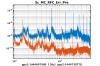
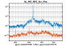
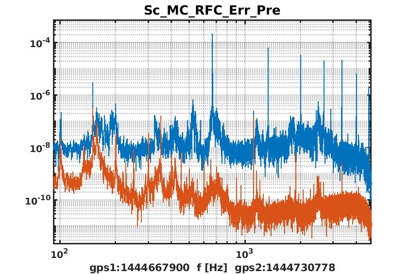
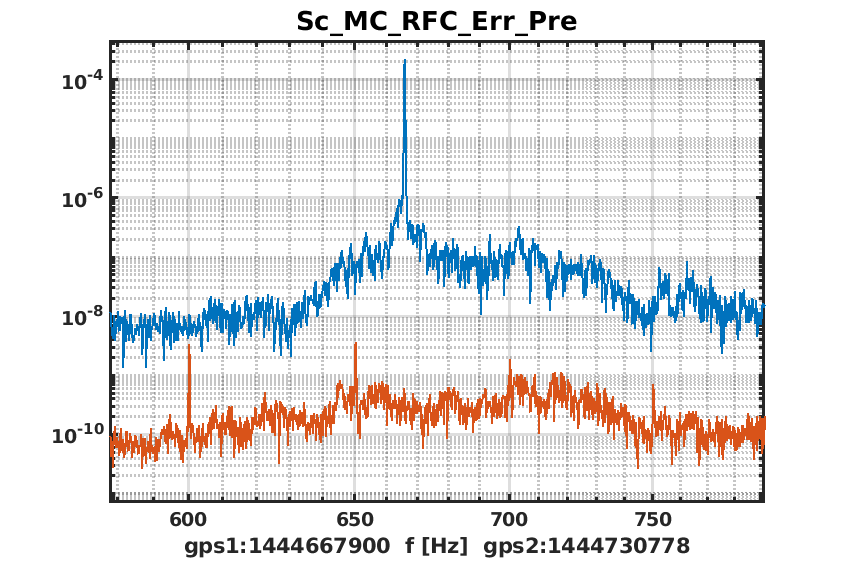
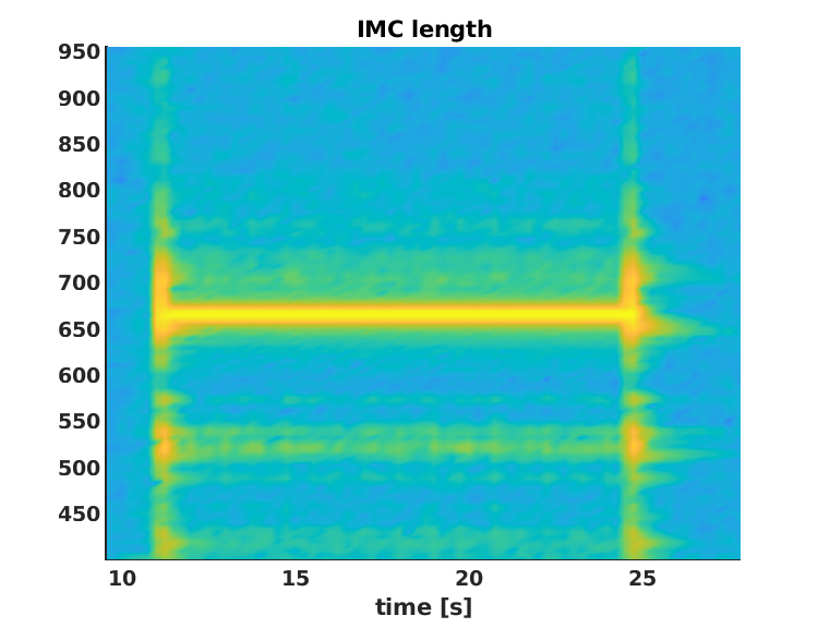
From previous test, we know that such a movement induces an excess of frequency noise that causes the IMC to unlock when the RFC is also locked. The noise is mainly due to a resonance at high frequency (~670Hz), most probably due to the way the actuator itself works (e.g. one sign is the presence of the harmonics at similar amplitude).

In order to have workable data, we worked with INJ in standalone and choose an appropriate looser filter for the lock of the RFC (already prepared in 2023), new filter applied at ~16.09UTC.
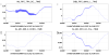
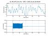
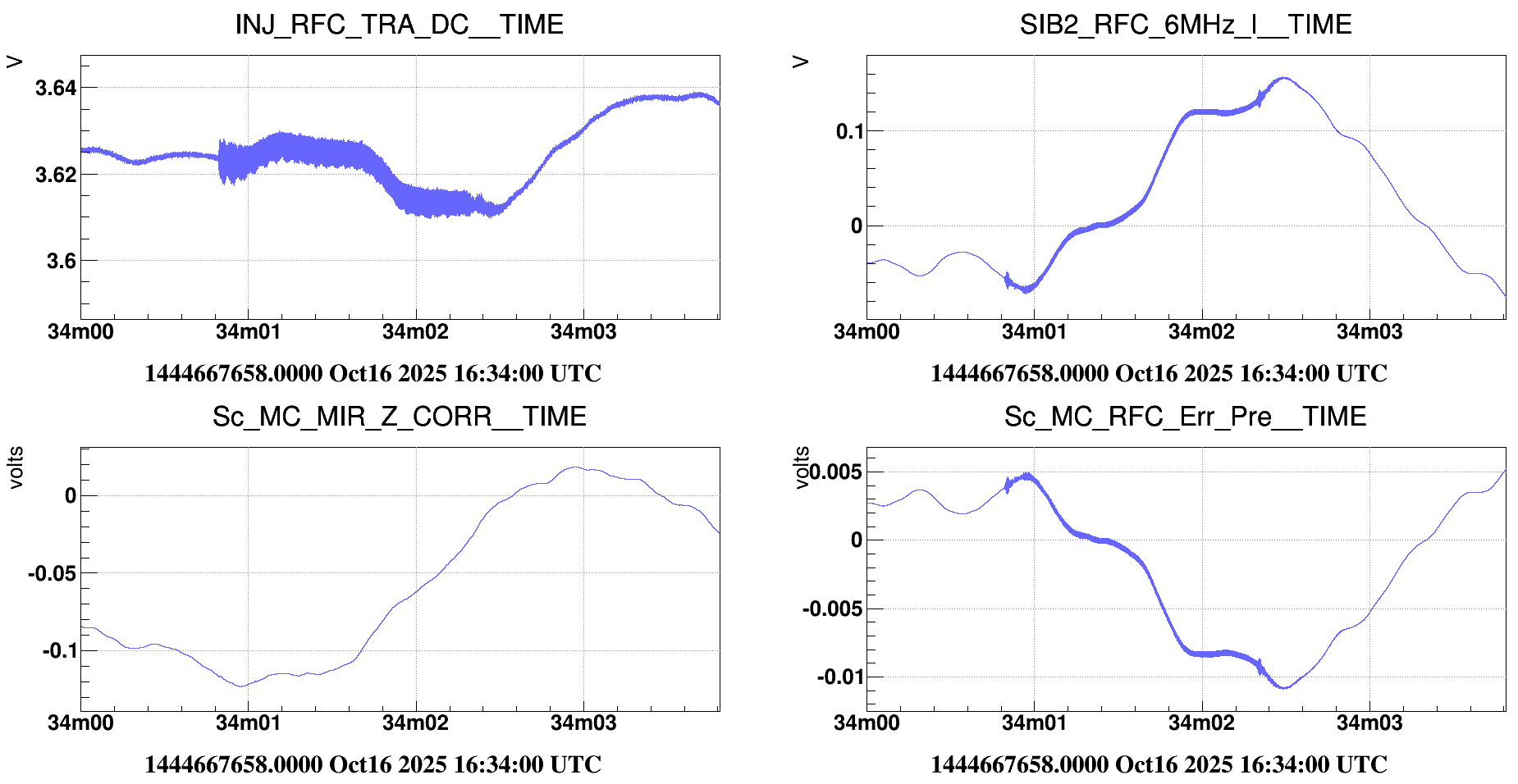
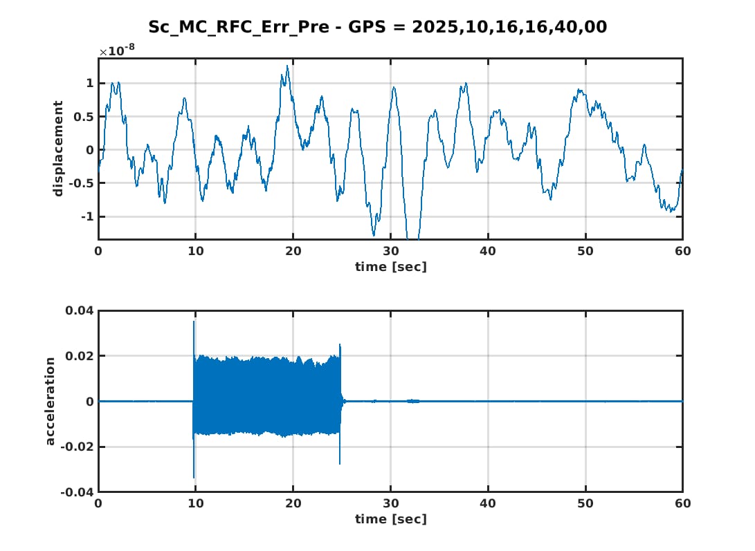
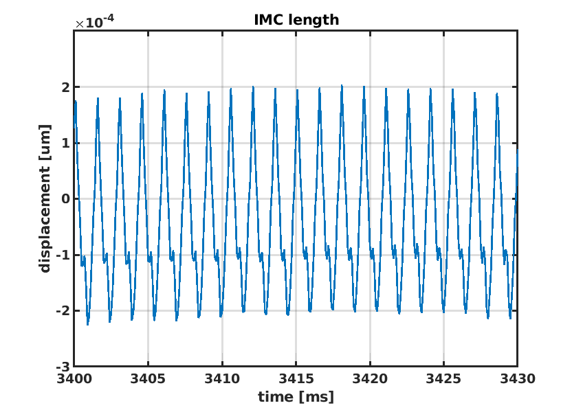
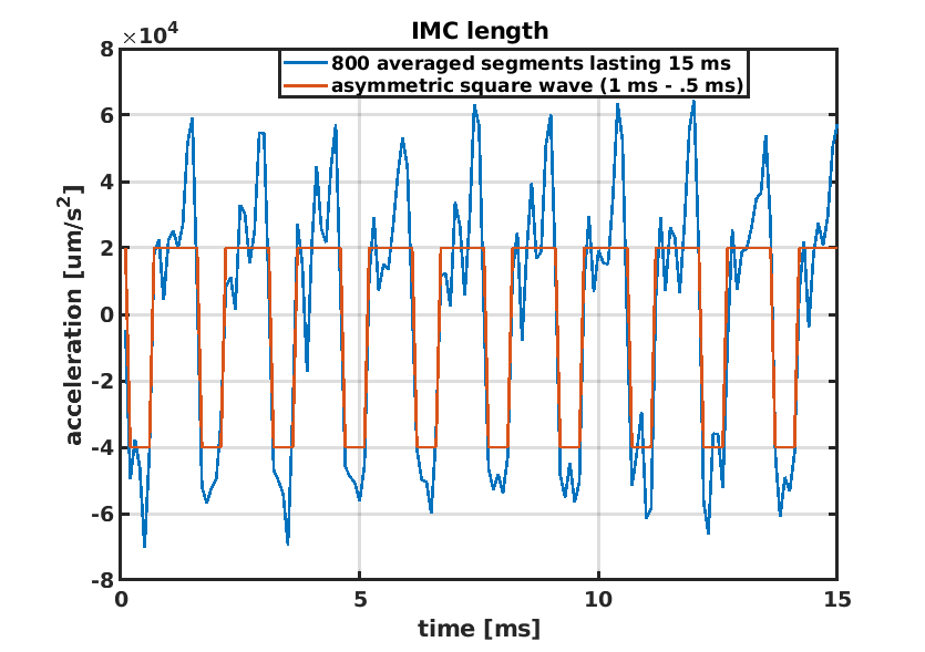
Then, we activated IPC2 several times (with different number of step, 100/1000/10000, back and forth, list of GPS at the end of the entry), the effect of the movement is visible on several INJ signals, in particular on the RFC_TRA and RFC error signal (see fig. 1). The latter being calibrated in µm, we directly have the movement of the bench due to the rotator action, and consequently the force applied by the rotator (fig. 2).

In the next days, assuming that what we read in the RFC err signal is only the bench motion (in the simplified hypothesis that the dihedron is rigid wrt the bench), we will use those data to estimate the effect of the IPC2 on the PRM1 mirror, using the estimated force as an input mechanical transfer from bench to PR1 mirror.

At the end of the shift we put the IPC2 back to the ~100% of transmission and relocked correctly in LN3.


GPS of usuful actions on IPC2:
2025-10-16-16h09m15-UTC    info spinicelli   'Move IPC2 [Channel=1,Axis=1,Displacement=10,Step Amplitude=50]' sent to Sib1AgilisRot
2025-10-16-16h10m04-UTC    info spinicelli   'Move IPC2 [Channel=1,Axis=1,Displacement=100,Step Amplitude=50]' sent to Sib1AgilisRot
2025-10-16-16h11m11-UTC    info spinicelli   'Move IPC2 [Channel=1,Axis=1,Displacement=-100,Step Amplitude=50]' sent to Sib1AgilisRot
2025-10-16-16h34m00-UTC    info spinicelli   'Move IPC2 [Channel=1,Axis=1,Displacement=1000,Step Amplitude=50]' sent to Sib1AgilisRot
2025-10-16-16h38m01-UTC    info spinicelli   'Move IPC2 [Channel=1,Axis=1,Displacement=9000,Step Amplitude=50]' sent to Sib1AgilisRot
2025-10-16-16h40m12-UTC    info spinicelli   'Move IPC2 [Channel=1,Axis=1,Displacement=-10000,Step Amplitude=50]' sent to Sib1AgilisRot
2025-10-16-16h59m43-UTC    info spinicelli   'Move IPC2 [Channel=1,Axis=1,Displacement=1000,Step Amplitude=50]' sent to Sib1AgilisRot
2025-10-16-17h00m23-UTC    info spinicelli   'Move IPC2 [Channel=1,Axis=1,Displacement=-1000,Step Amplitude=50]' sent to Sib1AgilisRot
2025-10-16-17h15m20-UTC    info spinicelli   'Move IPC2 [Channel=1,Axis=1,Displacement=1000,Step Amplitude=50]' sent to Sib1AgilisRot
2025-10-16-17h16m27-UTC    info spinicelli   'Move IPC2 [Channel=1,Axis=1,Displacement=-1000,Step Amplitude=50]' sent to Sib1AgilisRot

To be noted: the last two displacements correspond to a trial to observe the same effect with the arms locked and a different filter (i.e. UGF reduced at ~60Hz). Despite a clear higher frequency noise of the arms, the movement of the rotator itsefl didn't directly unlocked neither the IMC or the arms, but it did it after few seconds. Most probably, the drop in arm power caused by the movement  triggered some threshold in the automation to unlock.

Images attached to this report
Comments to this report:
chiummo - 14:57 Friday 17 October 2025 (67968) Print this report

If I get this correctly, the acceleration inferred from the calibrated signal is of the order of 0.02 m/s^2 (???: no units in the plot), so if we assume the whole SIB1 is moving, shaken by the rotator, a force of the order of F~100Kg * 0.02 m/s^2 = 2 N is applied by the rotator to the bench. I am no expert but this seems very large.

A different working hypothesis put forward in the past was that the rotation of the waveplate excites some resonance of the dihedron or its support, which is a much lighter mass. It could be important to discriminate between the two hypotheses in order to steer future upgrades. For instance, one could try to improve the mechanical isolation of the dihedron with respect to the SIB1, or to increase the damping of possible mechanical resonances of the dihedron, and then repeat the experiment.

ruggi - 19:39 Friday 17 October 2025 (67971) Print this report

The spectrum of IMC length when the rotator is moving is dominated by a huge and narrow line at 666 Hz, together with all the harmonics (fig 1). Such a narrow line is not present in the frequency noise at LN3 (red curve, see also the zoom in fig 2). There are bumps, excited during the experiment and present in the clean data: one of them is around the line. One can look also at the spectrogram (fig 3): when the rotator stops, the shake excites large structures (one quite close to the line, but not exactly coincident), that roll down quickly. This is not exactly what one would have expected if the narrow line were simply due to the mechanics of the dihedron. Anyway, a structure at that frequency is present. The Q is not to big, but in case it is the resonace of the dihedron, for sure it amplifies the effect of the noise injection.

Very interesting the shape of the time domain signal produced when the rotator is moving (fig 4): a perfect periodicity and a high non-linearity is visible also there. In order to better characterize that signal, I have divided the data (12 seconds) in 800 segments lasting 15 ms each, containing in such a way exactly 10 oscillations. Making the average of all the segments, the 10 oscillation are still perfectly visible. I show what happens if one does the same with the second derivative of the signal: a square wave appears (fig 5). The shape is clearly asymmetric:  1 ms up, 0.5 ms down, with a doubled amplitude with respect to the upper level. Everything seems too precise to be 'natural'. Hopefully the explanation of this shape can be found in the data sheet of the rotator.

Images attached to this comment
mwas - 9:48 Saturday 18 October 2025 (67975) Print this report

666Hz is the expected frequency of the motion of the rotator. The documentation (https://www.newport.com/p/AG-UC8) list for speeds, 5 steps per second, 100 step per seconds, 1700 steps per seconds and 666 steps per second. From what I remember from the rotator on SDB1, 666 steps per second is the default speed. It is very likely that the steps are done through some square wave applied on the piezo element that makes the rotation. So the measured line at 666Hz in the IMC length corresponds well to the expected mechanical motion created by the rotator as it moves.

mwas - 9:13 Monday 20 October 2025 (67987) Print this report

A force of 2N for the piezo motor is actually what one should expect from the specification. The rotator doesn't list a force, but the linear translation stage that use the same piezo-motor and the same driver has a holding force of 4N and has a force of 2N to move up and down a load: https://www.newport.com/f/agilis-piezo-motor-linear-stages


Search Help
×

Warning

Error

The present report has been modified outside this window. Please check for its integrity in the main page.

Refreshing this page will move this report into drafts.

×