Reports 1-1 of 1 Clear search Modify search
Environmental Monitoring (Environmental Monitoring)
fiori, tringali, Paoletti - 19:50 Saturday 23 March 2024 (63714) Print this report
Test of automated injections using ENV_MAIN

This is a follow up of https://logbook.virgo-gw.eu/virgo/?r=63649

Friday afternoon we used two hours of commissioning to test the ENV_MAIN metratron node. The ITF was locked in LOW_NOISE_3_SQZ, COMMISSIONING.

WE performed this sequence of environmental injections:

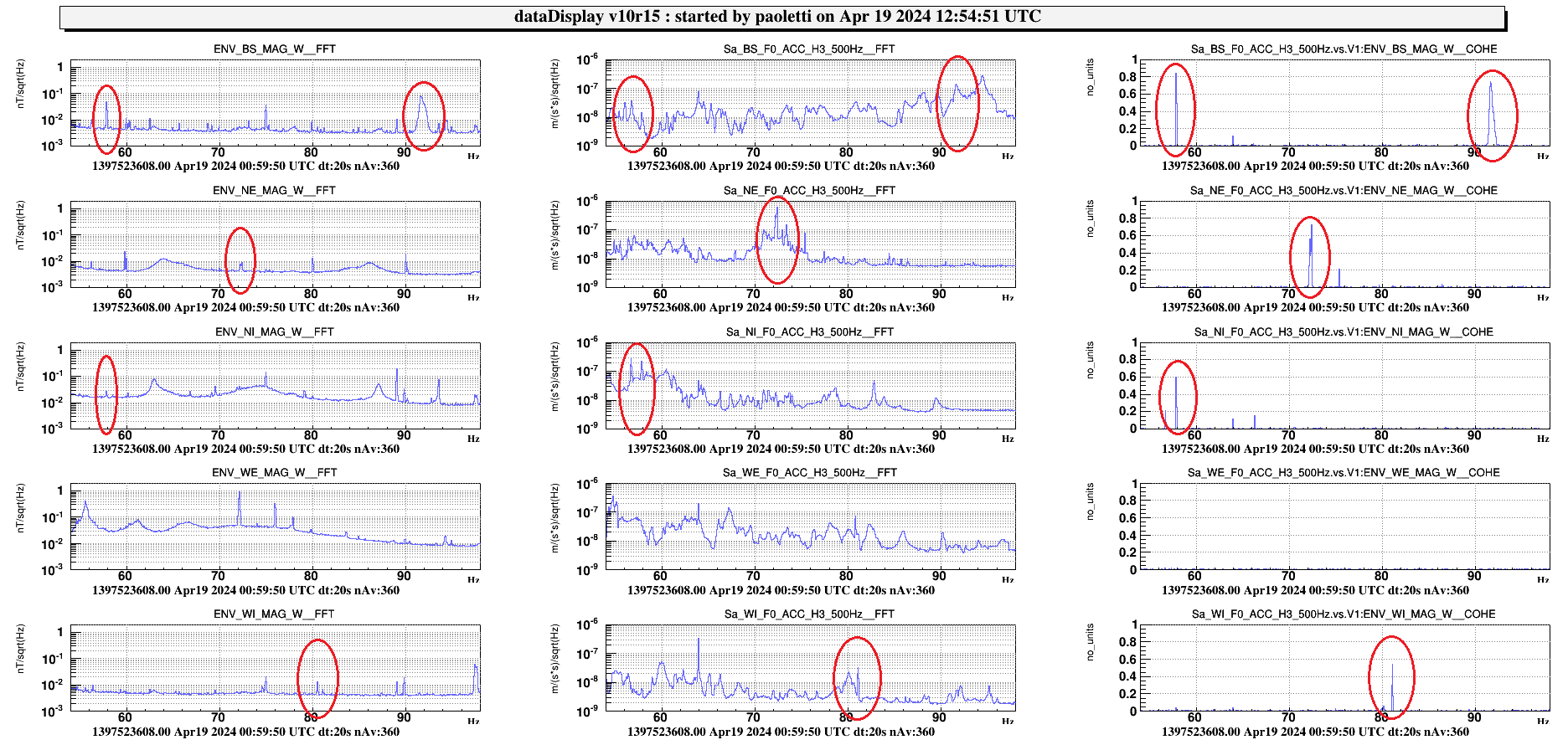
  • magnetic injection far field in CEB with the wall coil: 300s, sweep 8 Hz to 1000 Hz, 9V to the DAC
  • magnetic injection far field in NEB with the wall coil: 300s, sweep 8 Hz to 1000 Hz, 9V
  • magnetic injection far field in WEB with the wall coil: 300s, sweep 8 Hz to 1000 Hz, 9V
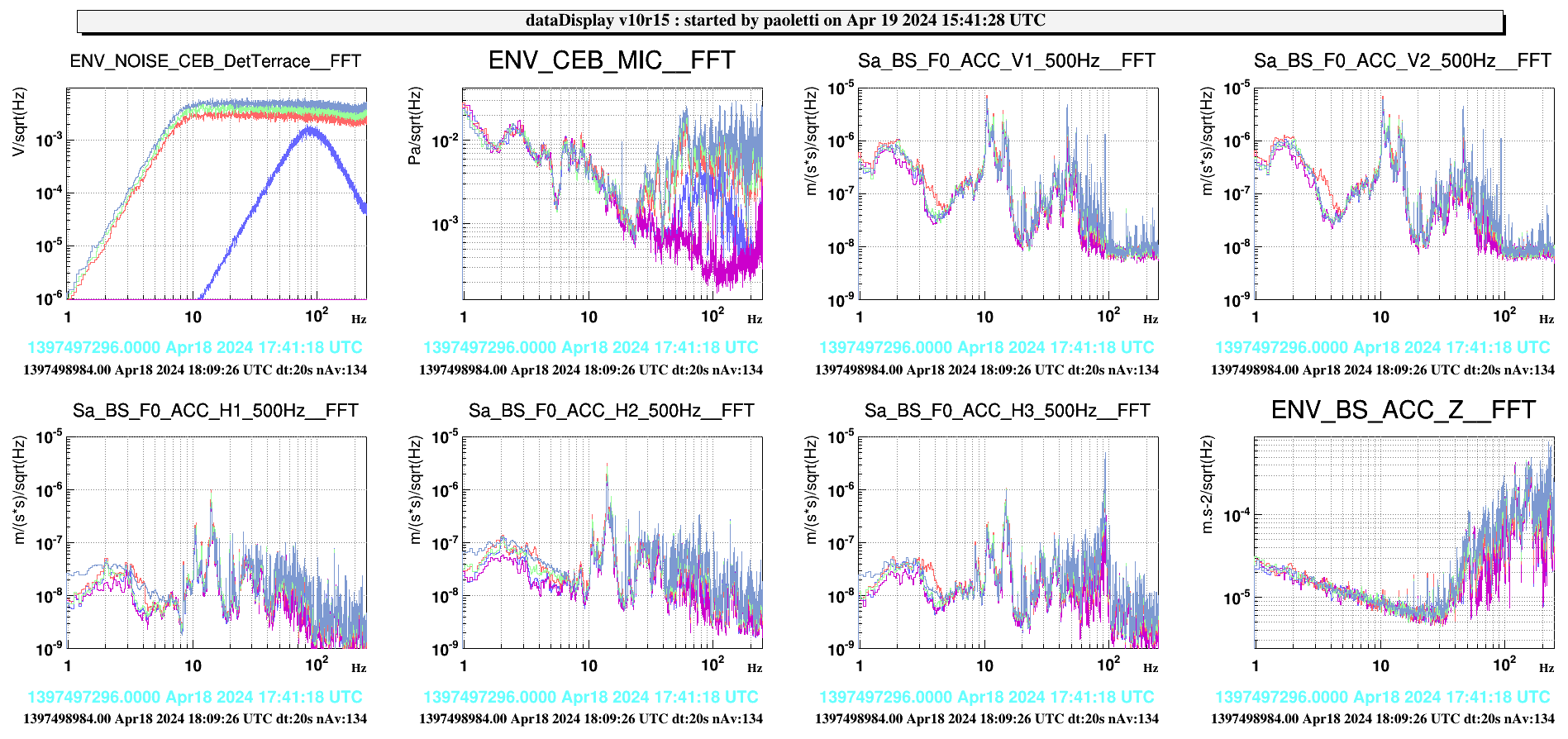
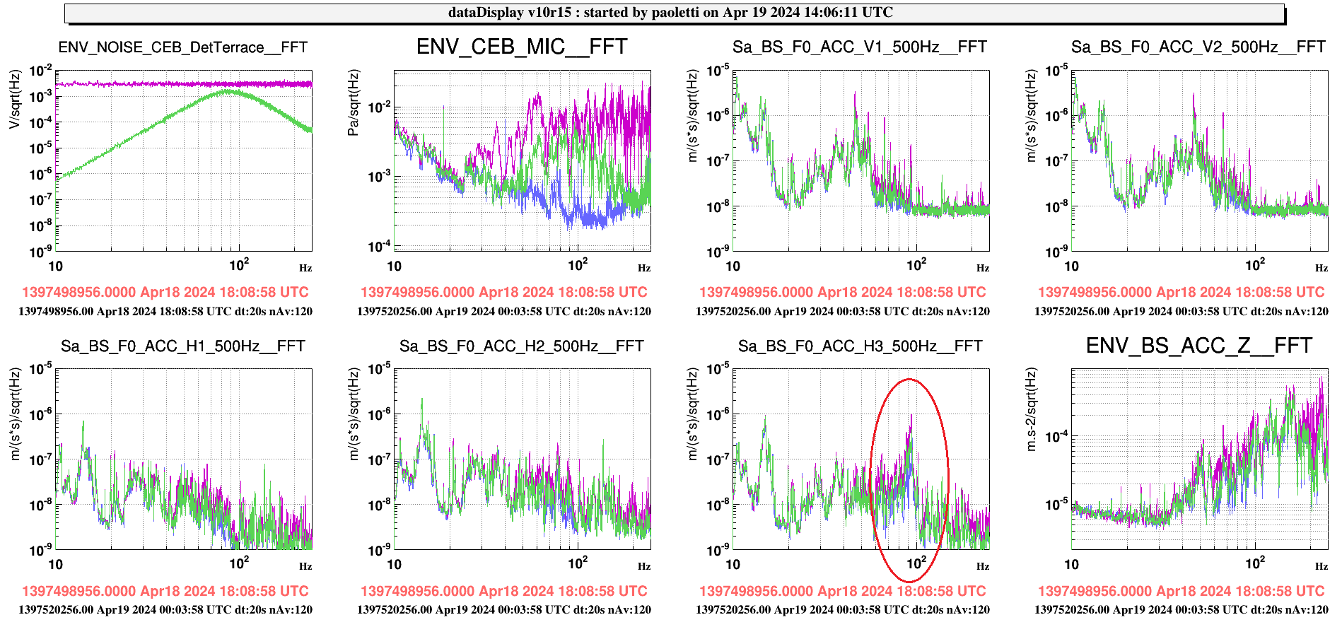
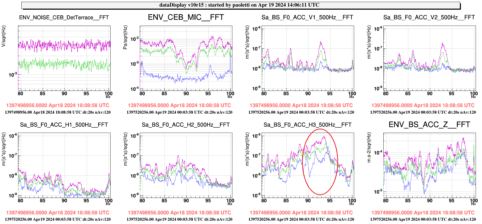
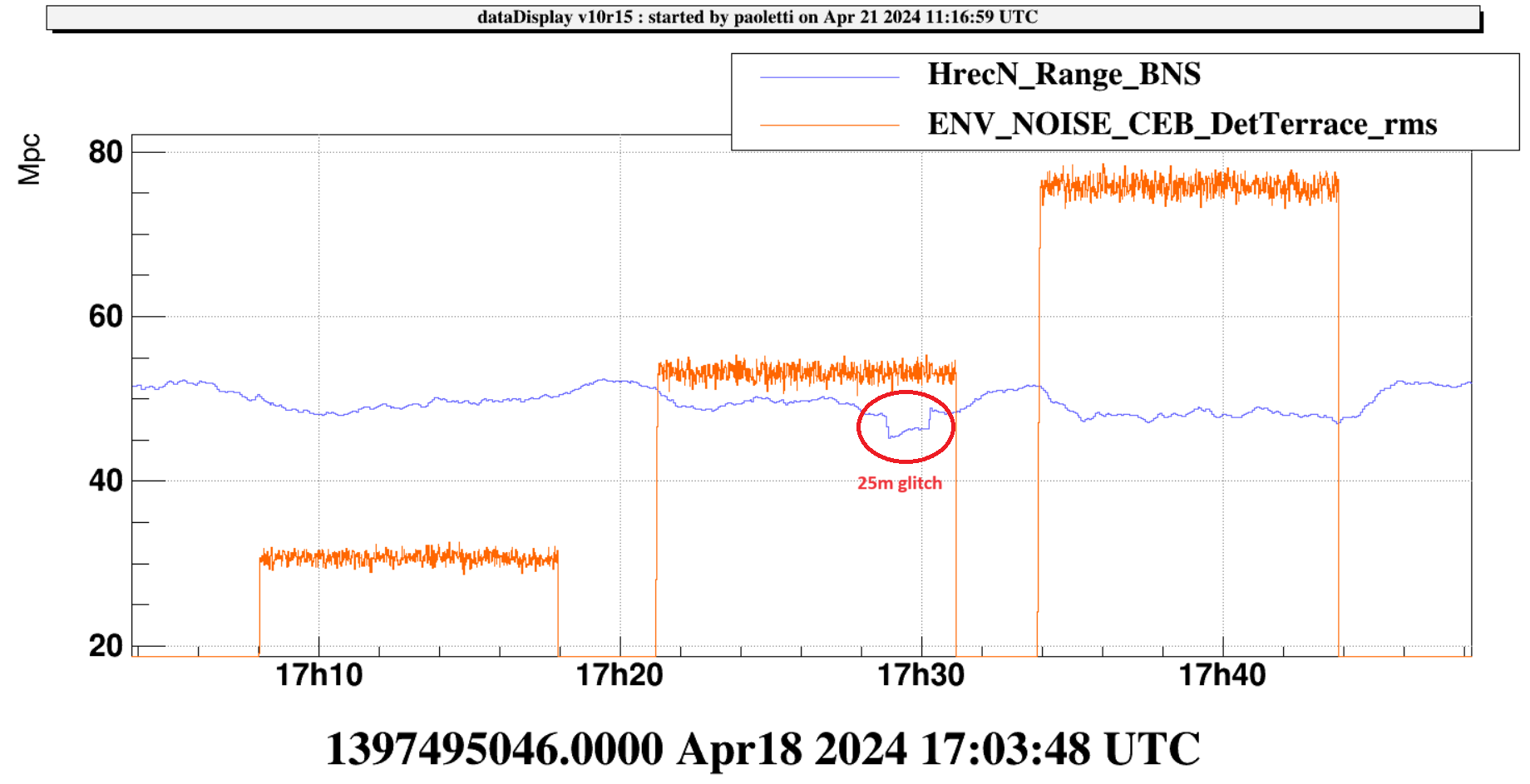
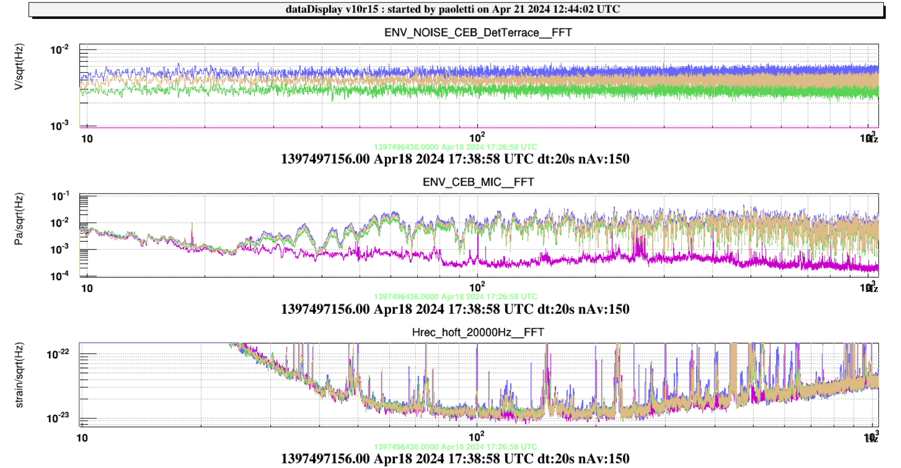
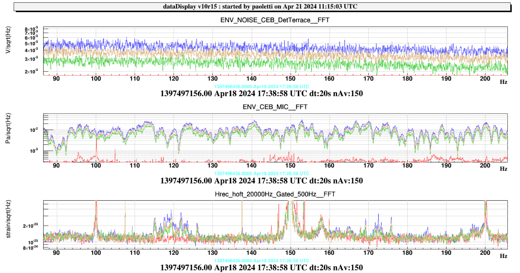
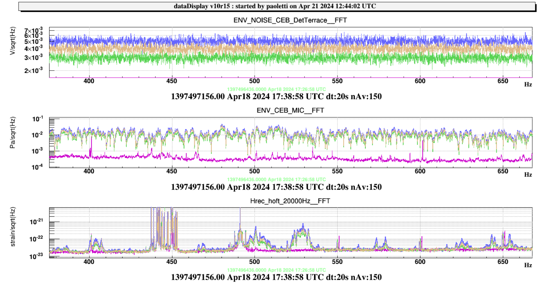
  • acoustic injection in the CEB  with the loudspeaker positioned in the DET terrace: 60s colored noise 8 - 2000 Hz, 0.025 V to the DAC

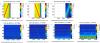
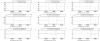
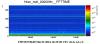
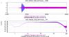
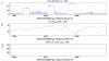
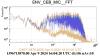
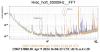
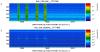
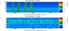
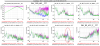
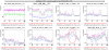
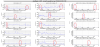
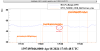
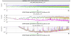
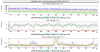
The magnetic injection was succesfully performed at CEB, NEB and NEB (Figure 1). The 9V amplitude although close to the limits for current (6Apk) and Voltage (70Vpk) did not saturate the amplifier (Figure 2). With this amplitude the signal is seen sufficiently well in hrec for NEB and WEB up to about 100Hz. For CEB the signal in hrec looks not so loud (Figure 3) but we might gain a bit by doubling the injection time to 600s. For NEB and WEB the Bartington magnetometers ENV_NE(WE)_MAG_V,N,W placed close to the NE(WE) tower have to be used for the coupling function computation,  because the metronix magnetometers on NEB and WEB saturate for the low frequency part of the sweep.

The output files were successfully produced in the designated directory: /virgoData/NoiseInjections/MagneticInjectionsO4/output/ and /virgoData/NoiseInjections/AcousticInjectionsO4/output/

One thing that is useful to be implemented in is that once the sweep injection is concluded a few seconds are waited before switching off the amplifier.

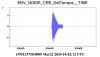
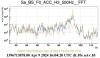
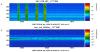
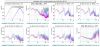
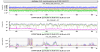
Instead the acoustic injection did not preform as expected because the large spike noise at the beginning of the injection appeared again (!) and of course unlocked the ITF: Figure 4

Indeed, to our understanding this should not have happened since the used

/virgoDev/Automation/userapps/ENV_MAIN.py

now points to the patched version of the code (v2r1p1), which when tested by launching the AcousticInjectionCEB process from the VPM performed ok (i.e. no spike)

.... reading from the ENV_MAIN.py:

#        noise_injection_script = "/virgoDev/EnvSwepts/v2r2/Linux-x86_64-CL7/bin/AcousticColoredInjection-conda /virgoData/NoiseInjections/ENV/AcousticInjectionCEB.cfg"
        noise_injection_script = "/virgoApp/EnvSwepts/v2r1p1/Linux-x86_64-CL7/bin/AcousticColoredInjection-conda /virgoData/NoiseInjections/ENV/AcousticInjectionCEB.cfg

We need Franco or Rhys to have a look into this.

Images attached to this report
Comments to this report:
fiori, tringali, paoletti, masserot - 18:28 Monday 15 April 2024 (63970) Print this report

The issue with the extra spike at the beginning of the colored noise injection was related to time settings in the ACL commands in the ENVnoise process. These modifications were made by Alain (on March 26):

OLD
# commamd - name of output channel - units - output sampling frequency - duration of 0 to 1 transition (s) - duration of 1 to 0 transition (s) - state of transition at startup (see ACL manual)
ACL_RELAY_CH                noise_filter_enbl    "au"    SAMP_FREQ    10    1    1  : the bold 1 means that the relay is equal to 1 at the starting time
# nameOut - unit - rampTime - samplingFreq - density - seed
ACL_NOISE_CH                noise_white            "V"     5    SAMP_FREQ    0.1    : idem the amplitude of the noise at starting time is set to 0.1
NEW
# commamd - name of output channel - units - output sampling frequency - duration of 0 to 1 transition (s) - duration of 1 to 0 transition (s) - state of transition at startup (see ACL manual)
ACL_RELAY_CH                noise_filter_enbl    "au"    SAMP_FREQ    10    1    0 :  relay set to 0 at starting time
# nameOut - unit - rampTime - samplingFreq - density - seed
ACL_NOISE_CH                noise_white            "V"     5    SAMP_FREQ    0.0   : noise amplitude set to 0 too

Figure 1 shows the result of the test: blue is with the OLD settings, purple is the with the NEW settings (the same colored noise with amplitude 0.025 V has been injected in both cases). The spike is no longer present.

The same test was done by injecting the colored noise from the ENVnoise and also using the ENV_MAIN node which calls the AcousticInjectionCEB process.

Images attached to this comment
fiori, tringali, ruggi - 23:26 Monday 15 April 2024 (63972) Print this report

On April 9 we performed a set of short (60s) colored acoustic injections in the CEB. The ITF was locked in LOWNOISE 3 since a few minutes.

The purpose was to tune the level of the injection in such a way to avoid triggering the 92 Hz oscillation of the BS F0 accelerometers (mostly Sa_BS_F0_ACC_H3) which caused unlocks in the past (https://logbook.virgo-gw.eu/virgo/?r=63709). The purpose of the present test was not to understand the nature and physical reason of the oscillation onset, which remains to be understood.

We injected colored noise between 20 and 2000Hz with 3 levels: 0.03 V, 0.04 V and 0.05 V, one 25min glitch occurred right at the beginning of the 0.05 V injection (Figure 1).

The intensity on the acoustic noise produced in the hall, measured in the position of the hall microphone, was of the order of a factor 20 above the quiet condition (Figure 2). The 92 Hz oscillation of  the BS F0 ACC H3 accelerometer onsets already with the 0.03 V but  amplifies x5 and x10 when the injected level increases from 0.03V to 0.04V and from 0.03V to 0.05V, respectively (Figure 3).

Figure 4 shows the impact on hrec. The noise in hrec increased at some structures, mostly known to be associated to SDB1. These excitations are well visible with all injected levels (Figure 5, which also shows the 25min glitch).

It seems to notice also an increase of the 74 Hz line (DARM loop gain) and the 227 Hz line (SSFS loop gain). As well, it seems to notice a small increase of the noise in the bucket. It seems that particularly the injection at 0.05 V, brings the ITF to a different working point where other noises (e.g. frequency noise) are more coupled.

However, spectrograms in Figures 6 and 7 indicate that the amplitude of 74 Hz and 227 Hz lines was not so stable during the injection period (we were at the beginning of a lock) and its correlation with single acoustic injections is not straightforward.

Paolo's suggestion is to better study this behaviour with longer injections.

Images attached to this comment
Fiori, Paoletti, Tringali - 20:14 Thursday 18 April 2024 (64024) Print this report

We performed a set of four acoustic injections in CEB with the AcousticInjectionCEB VPM process:

1) 17:07:55 UTC - (8 - 2000) Hz, 600 sec, 0.03 V

2) 17:21:05 UTC - (8 - 2000) Hz, 600 sec, 0.04 V  (25 min glitch at ~17:29:24 UTC)

3) 17:33:48 UTC - (8 - 2000 )Hz, 600 sec, 0.05 V

4) 18:04:40 UTC - (80 -100) Hz, 300 sec, 0.04 V

The directory path of output files is /virgoData/NoiseInjections/AcousticInjectionsO4/output. The list of file injections is reported below:

1) AcousticColored_NOISE_CEB_DetTerrace-1397495261.txt

2) AcousticColored_NOISE_CEB_DetTerrace-1397496052.txt

3) AcousticColored_NOISE_CEB_DetTerrace-1397496814.txt

4) AcousticColored_NOISE_CEB_DetTerrace-1397498666.txt

Paoletti, Fiori, Tringali - 18:02 Friday 19 April 2024 (64032) Print this report

We tested the sensitivity of the top-stage BS accelerometers at three different levels of acoustic injection (nominally 0.03 - 0.04 - 0.05 V).

Noise was filtered from 8 to 2000 Hz, but the actual noise produced was only from 20 Hz and up, as the speaker is unable to go lower.


The fourth injection (18:04:40 UTC - (80 -100) Hz, 300 sec, 0.04 V) aimed to produce the same level around the frequency of ~93 Hz (without generating out-of-band noise) where one of the horizontal BS F0 accelerometers (Sa_BS_F0_ACC_H3_500Hz) is usually excited during acoustic injections, in order to check whether the coupling is linear or not.

Unfortunately, the filter was too narrow, and the noise spectral density at 93 Hz was lower than expected.

However, we can say that generating a higher level by a factor of 2 (with no noise at lower frequencies) resulted in an increase of the peak by about a factor of 2 (difficult to estimate accurately). It appears that there is no upconversion and the system is "linear."


During this test we also noticed that there is some (unexplained) coherence between the upper stage F0 accelerometers and the lower external magnetometers (this is also the case in other towers besides BS).

At first glance one might think of general coupling due to the external accelerometer cables running not too far from the magnetometers (as indeed they are), but there are high-level signals in the acceleration spectrum that have no coherence. If it were a coupling from the cable, it should be broadband.

Images attached to this comment
Paoletti, Fiori, Tringali. - 15:18 Sunday 21 April 2024 (64048) Print this report
Images attached to this comment
Search Help
×

Warning

×