On 2019/01/17, when SDB2 minitower was opened, we measured the frequency dependent response of B1p_PD1_DC and B1p_PD2_DC channels.
These channels are used for actuator calibration in free swinging Michelson. They were assumed flat in frequency in the past, but we noticed it is not the case, since the impedance vary with frequency due to the presence of the Audio channel.
To measure it, we have installed a LED in front of the photodidoes, and excited the LED with 16 lines from 0.05 Hz to 210 Hz. The transfer function from the LED excitation to the DC channel gives the DC response shape. We have checked at LAPP that the DAC+LED has a flat response: applying the same excitation to the LED in front of a PCAl photodiode (a simple photodiode with a series resistor for sensing), the TF from the excitation to the photodiode readout was flat.
Time of the injections and measured transfer functions:
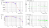
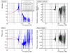
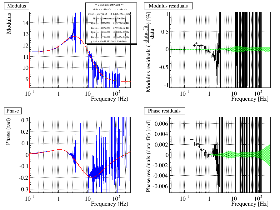
- injection on B1p_PD1: 17/01/2019, 12h58 LT-> 13h07m00 (from shutter open to shutter close) . --> figure 1. PD1 Audio channel its analog high-pass filter around 16 Hz.
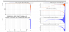
- injection on B1p_PD2: 17/01/2019, 13h15 LT-> 13h27m00 --> figure 2. PD2 Audio channel its analog high-pass around 2 to 3 Hz.
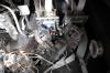
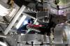
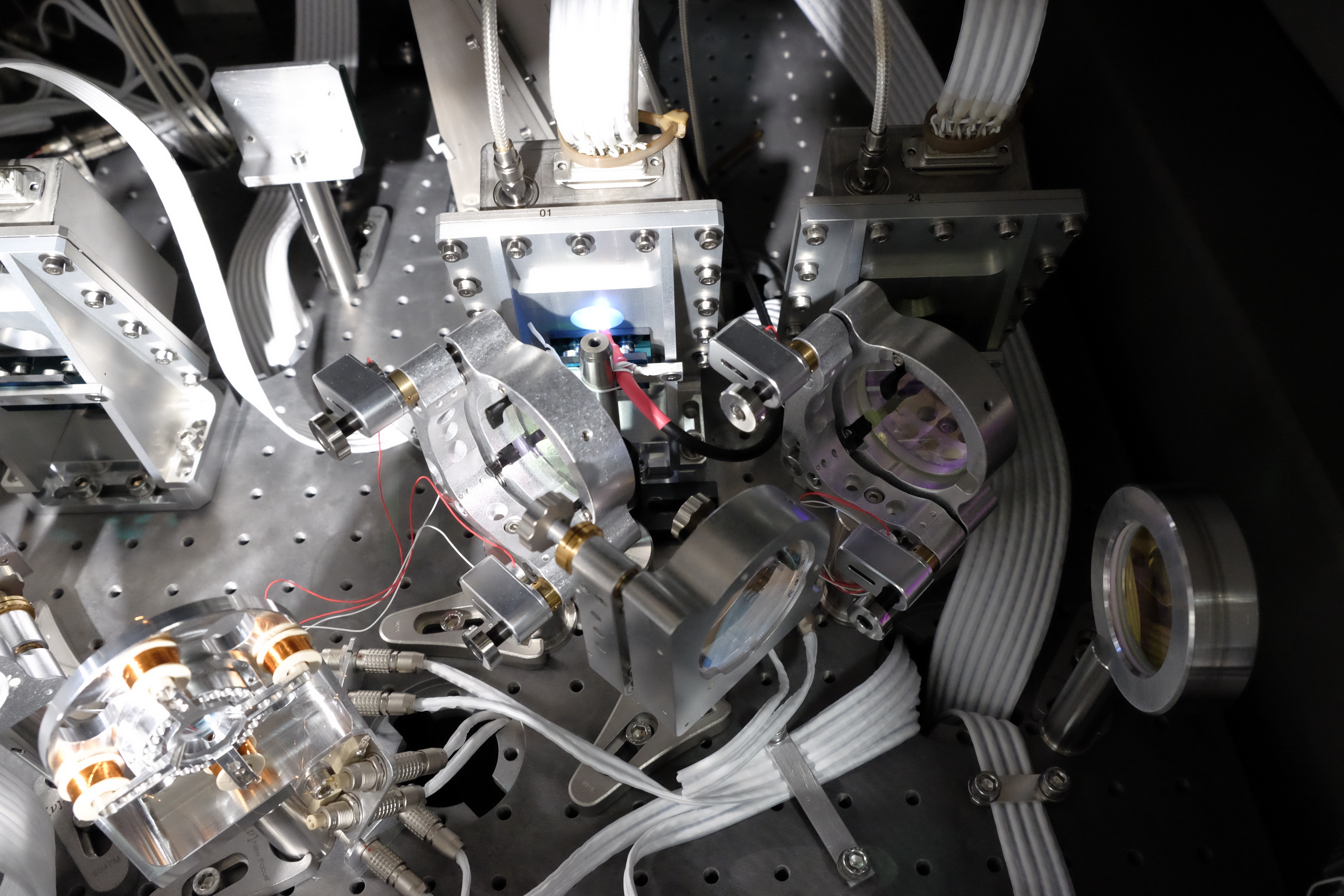
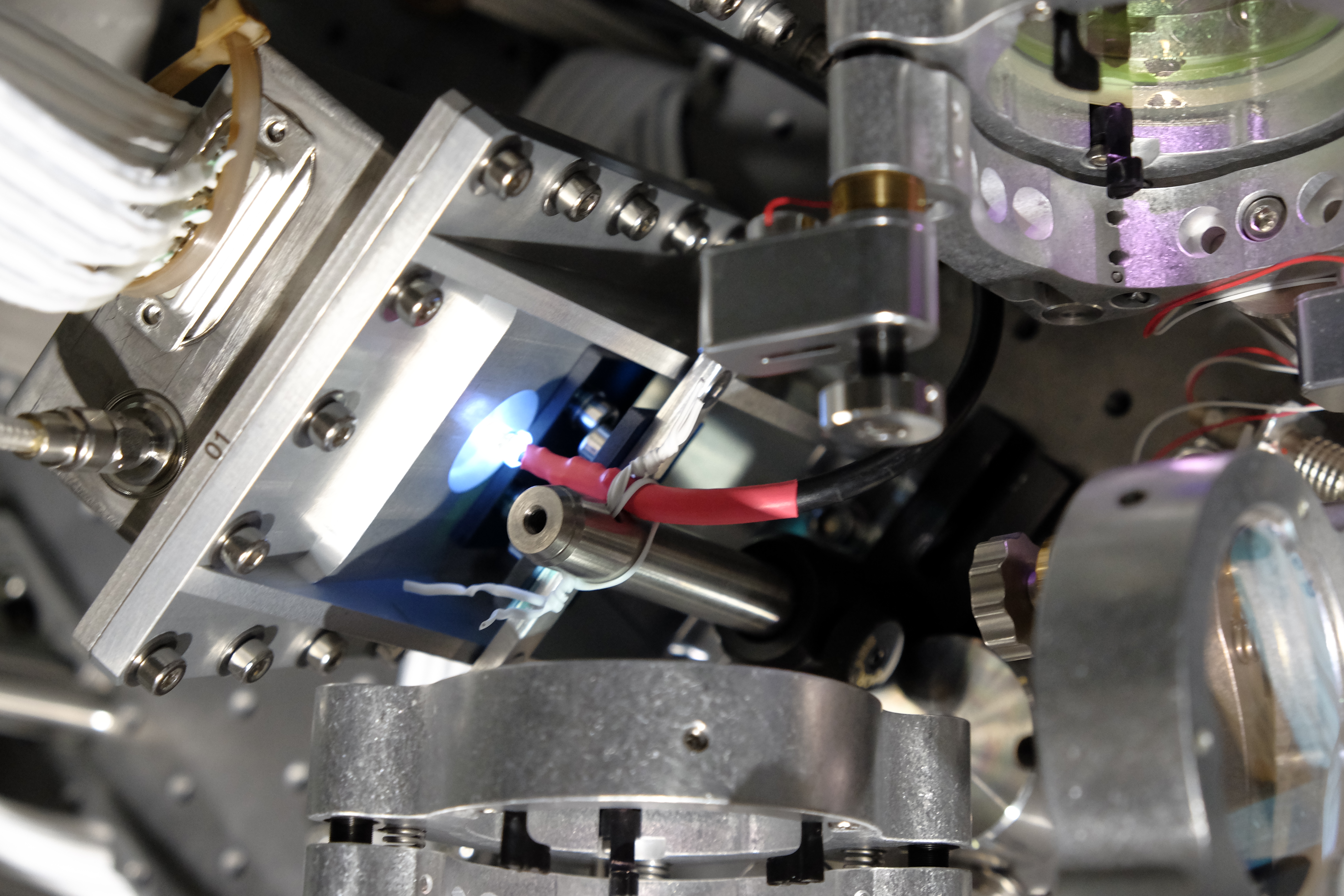
The figure 3 gives a picture of the LED installed in front of the photodiode B1p_PD2.
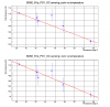
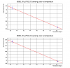
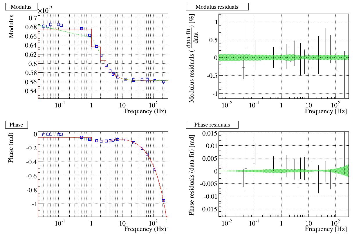
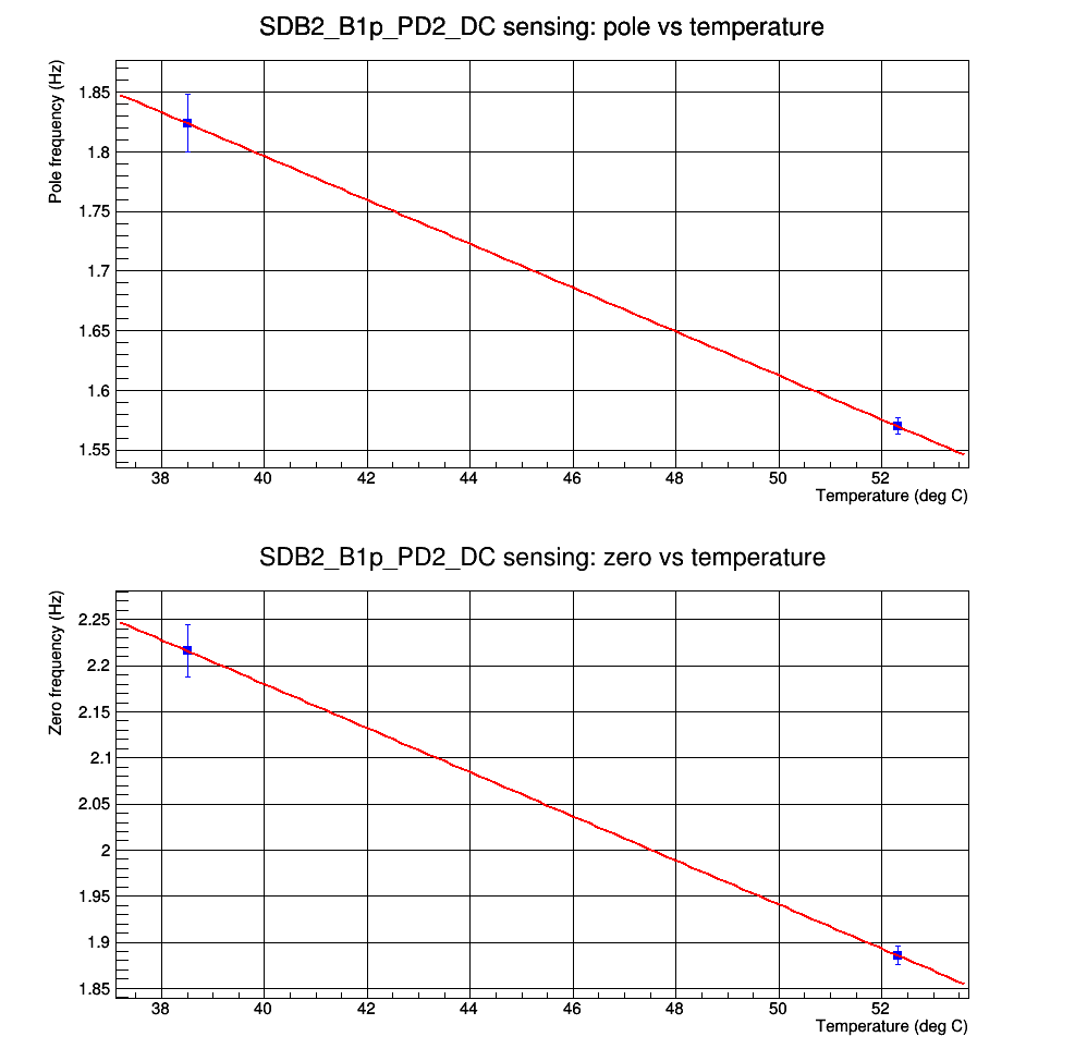
The transfer functions have been fitted with a simple pole and simple zero model. The parameteres of the fit are the following (the gain and delay are not relevant for the photodiode calibration and are not reported):
| B1p_PD1_DC | B1p_PD2_DC | |
| Pole (Hz) | 11.221 +/- 0.022 | 1.824 +/- 0.024 |
| Zero (Hz) | 17.247 +/- 0.035 | 2.216 +/- 0.028 |
| Chi2/ndf (proba) | 98.8/92 (29.5%) | 41.6/92 (99.9%) |
The cable and LED that was connected to the DAC1955 output has been left in the DET lab board for future measurements.
=======================
For the record, here is the list of injected signals, generated in the Acl config EDB
ACL_CONST_CH LED_offset "V" 1.0 SAMP_FREQ +4.0 #LED start blinking above 2.5-3 V
# nameOut - unit - rampTime - sampleRate - sinus ampl - sinus Freq(Hz) - phi0(rad) - offset(unit)
ACL_SINEWAVE_CH LED_sine1 "V" 1 SAMP_FREQ 0.1 0.05 0 0
ACL_SINEWAVE_CH LED_sine2 "V" 1 SAMP_FREQ 0.1 0.11 0 0
ACL_SINEWAVE_CH LED_sine3 "V" 1 SAMP_FREQ 0.1 0.51 0 0
ACL_SINEWAVE_CH LED_sine4 "V" 1 SAMP_FREQ 0.1 0.91 0 0
ACL_SINEWAVE_CH LED_sine5 "V" 1 SAMP_FREQ 0.05 1.51 0 0
ACL_SINEWAVE_CH LED_sine6 "V" 1 SAMP_FREQ 0.05 2.11 0 0
ACL_SINEWAVE_CH LED_sine7 "V" 1 SAMP_FREQ 0.05 3.11 0 0
ACL_SINEWAVE_CH LED_sine8 "V" 1 SAMP_FREQ 0.03 4.11 0 0
ACL_SINEWAVE_CH LED_sine9 "V" 1 SAMP_FREQ 0.03 5.11 0 0
ACL_SINEWAVE_CH LED_sine10 "V" 1 SAMP_FREQ 0.03 7.11 0 0
ACL_SINEWAVE_CH LED_sine11 "V" 1 SAMP_FREQ 0.05 13.10 0 0
ACL_SINEWAVE_CH LED_sine12 "V" 1 SAMP_FREQ 0.01 23.10 0 0
ACL_SINEWAVE_CH LED_sine13 "V" 1 SAMP_FREQ 0.01 43.10 0 0
ACL_SINEWAVE_CH LED_sine14 "V" 1 SAMP_FREQ 0.01 63.10 0 0
ACL_SINEWAVE_CH LED_sine15 "V" 1 SAMP_FREQ 0.05 110.10 0 0
ACL_SINEWAVE_CH LED_sine16 "V" 1 SAMP_FREQ 0.01 210.10 0 0
ACL_SUM_CH LED_sine "V" 1 1 LED_sine1 1 LED_sine2 1 LED_sine3 1 LED_sine4 1 LED_sine5 1 LED_sine6 1 LED_sine7 1 LED_sine8 1 LED_sine9 1 LED_sine10 1 LED_sine11 1 LED_sine12 1 LED_sine13 1 LED_sine14 1 LED_sine15 1 LED_sine16
ACL_SUM_CH LED_cmd_tmp "V" 1 1 LED_offset 1 LED_sine
ACL_CLIP_CH LED_cmd LED_cmd_tmp 0 +5
And channel sent to the DAC1955, with gain 2. A cable LEMO3 to BNC adapted to the DAC1955 output was used for the DAC.
ACL_DAC_CH dac1955_EDB_DAC_ch01 1 DAC1955_FREQ LED_cmd 0 2 "None" "ad1955-10v" ""

