This week, the Faraday Isolator on SDB1 has been replaced with the new low losses in-vacuum Faraday Isolator developed by the EGO optics group (VIR-0432C-17).
On Monday afternoon (Feb 12) we accessed the detection tower and installed a temporary laser setup in order to place references on the SDB1 bench for the positioning of the new low losses Faraday and the realignment of its transmitted beam, following a procedure similar to the one described in VIR-0037A-18. For this purpose we injected a YAG beam on the bench using an optical fiber terminated by a collimator mounted on SDB1. The laser was injected in the area between the dichroic mirror and the B1/B5 diaphragm. The beam injected in the old Faraday was aligned by using the tunable mount of the collimator and an additional folding mirror. Two Irises were placed in front of the Faraday Isolator, one iris was placed right after the two lenses L2 and L3, and a fourth iris in front of the OMC, to be served as reference for realigning the beam after the substitution of the Faraday.
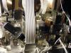
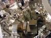
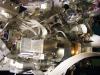
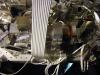
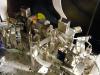
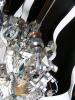
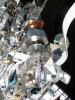
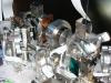
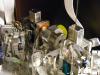
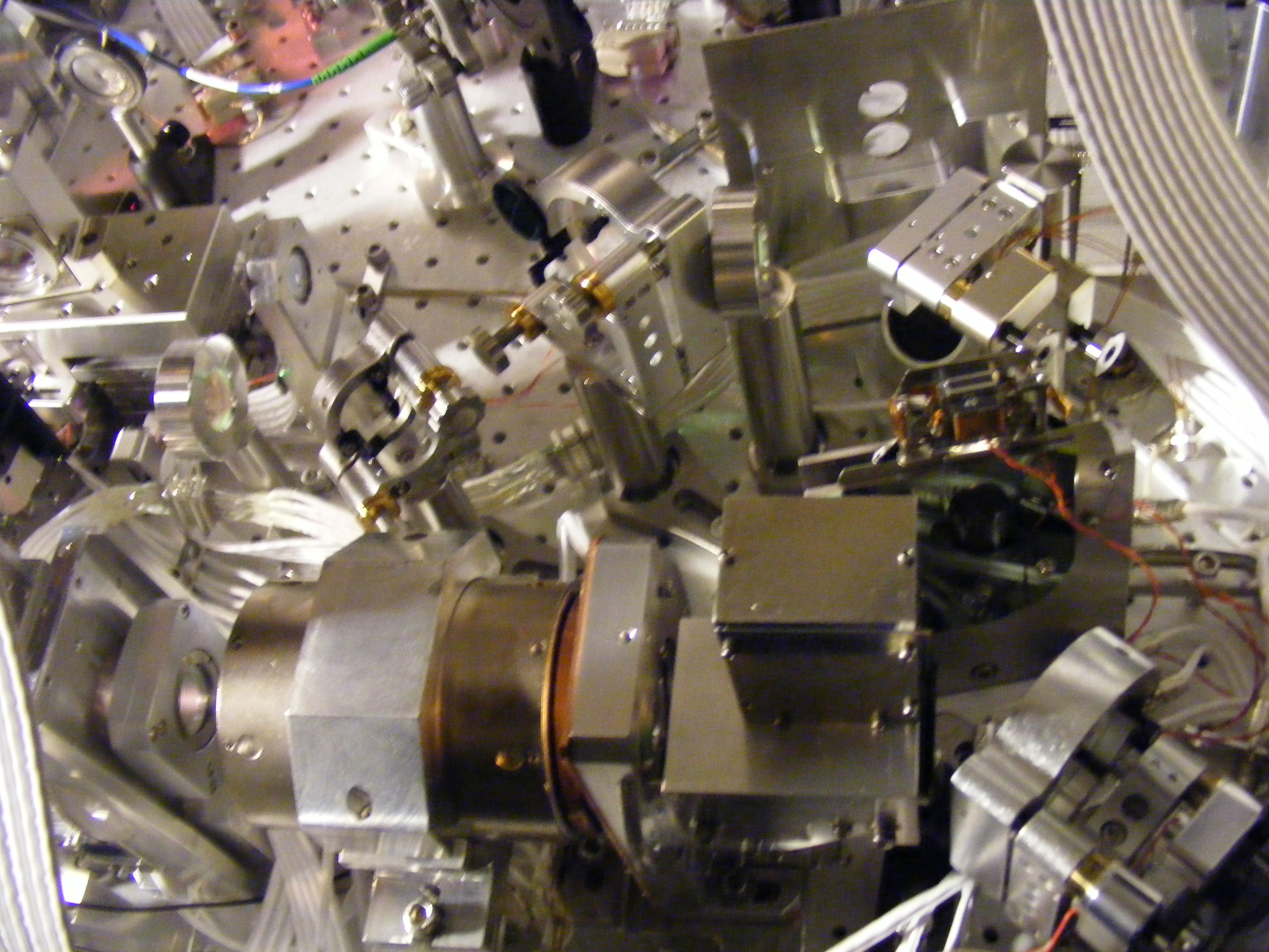
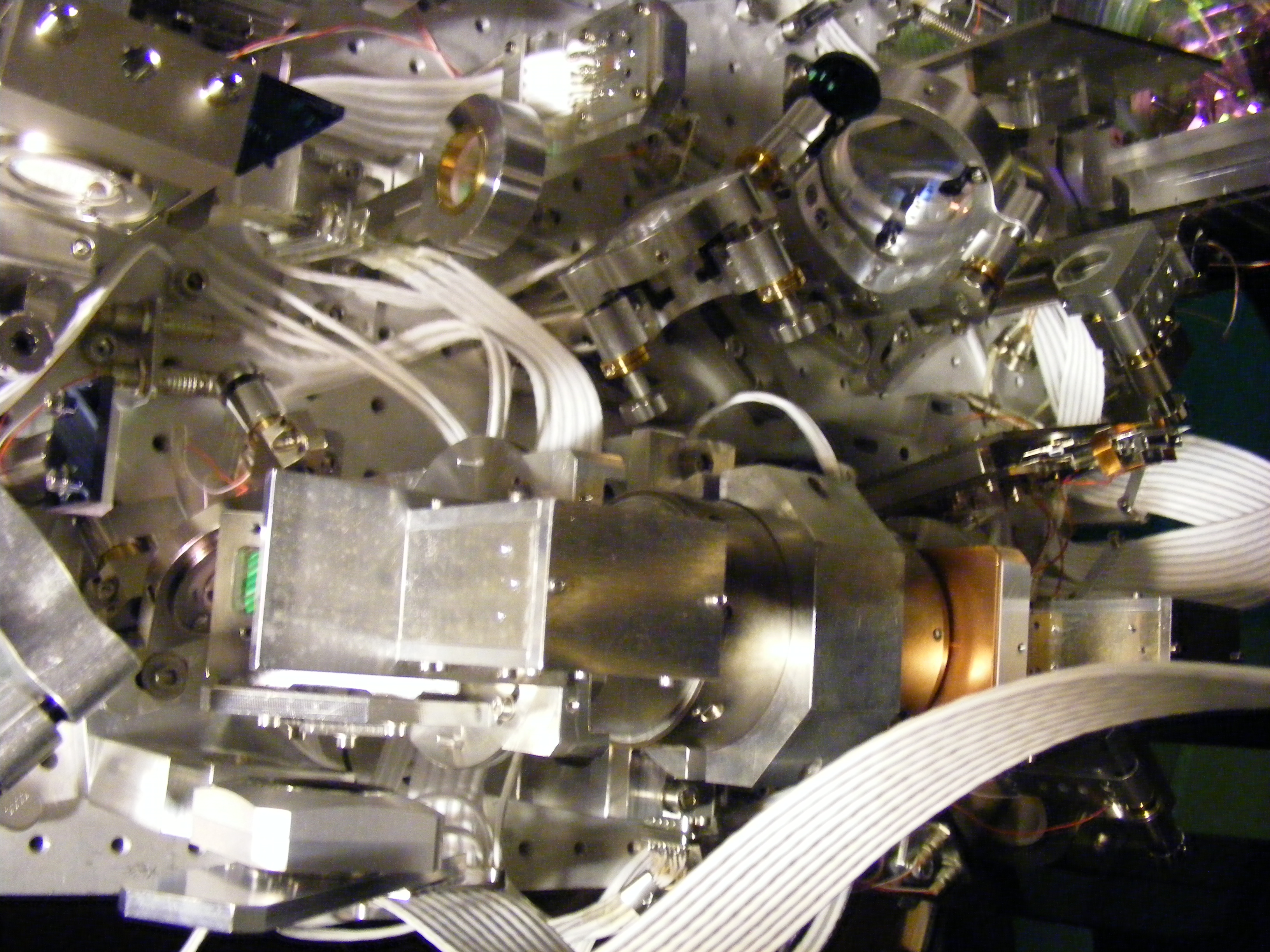
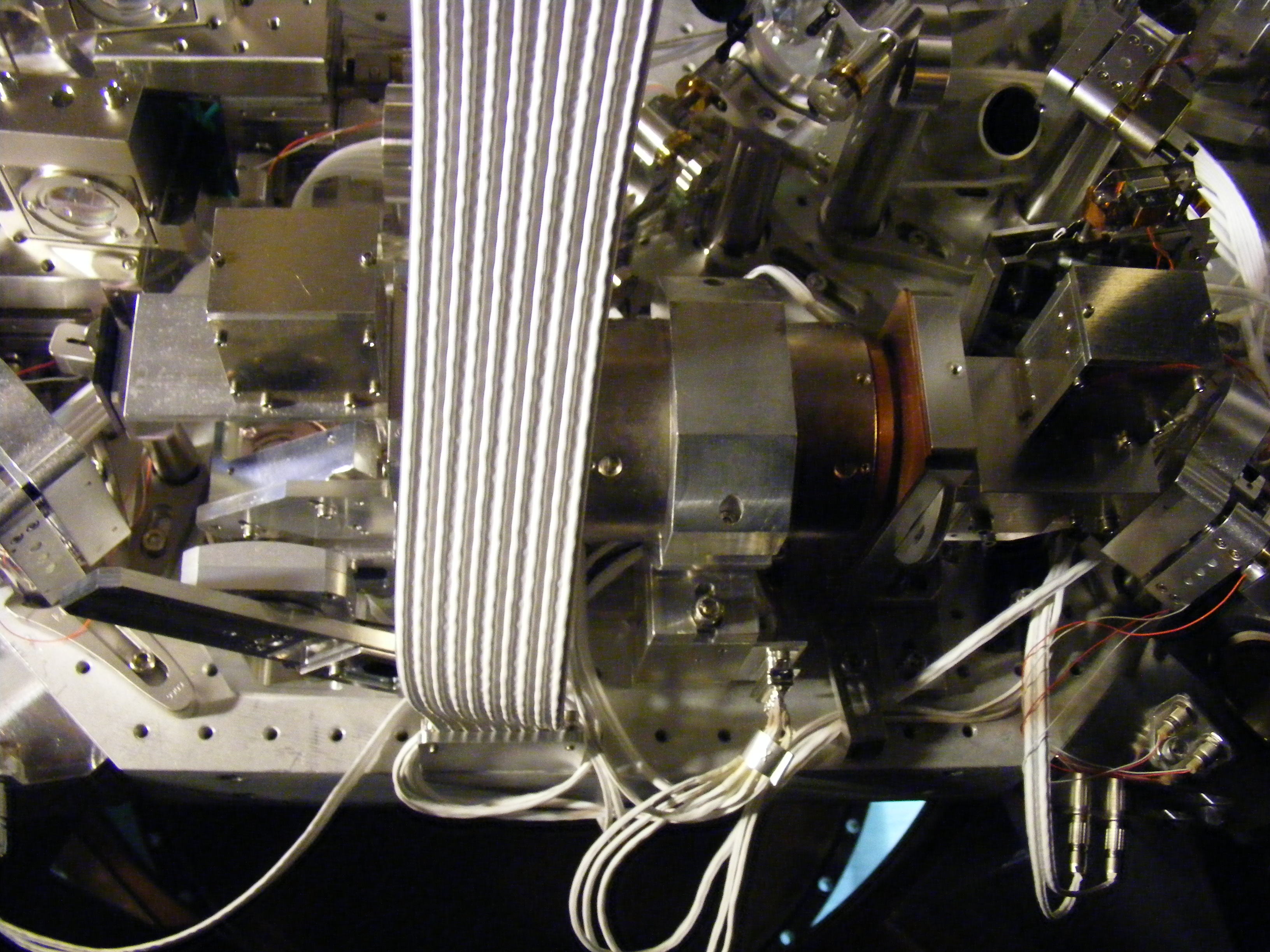
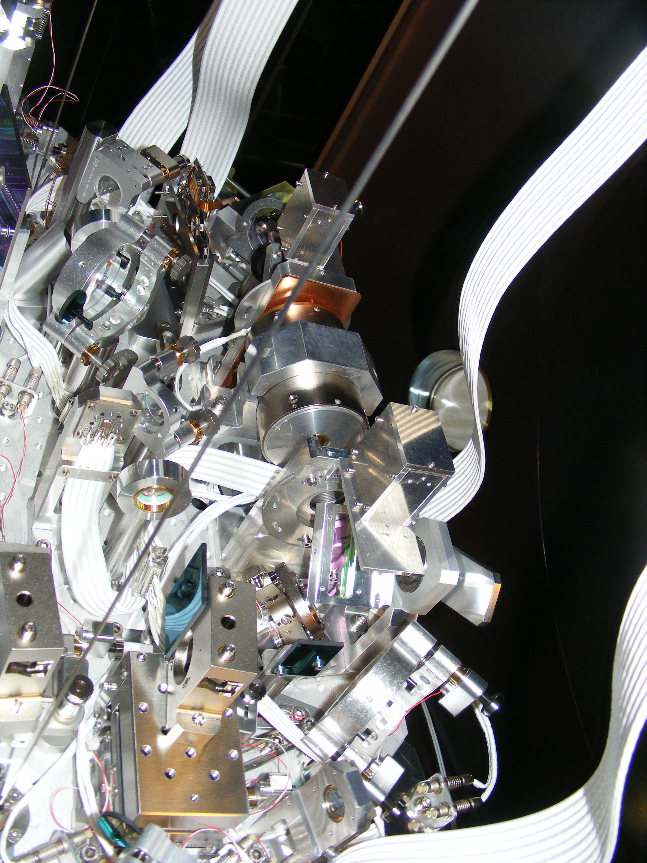
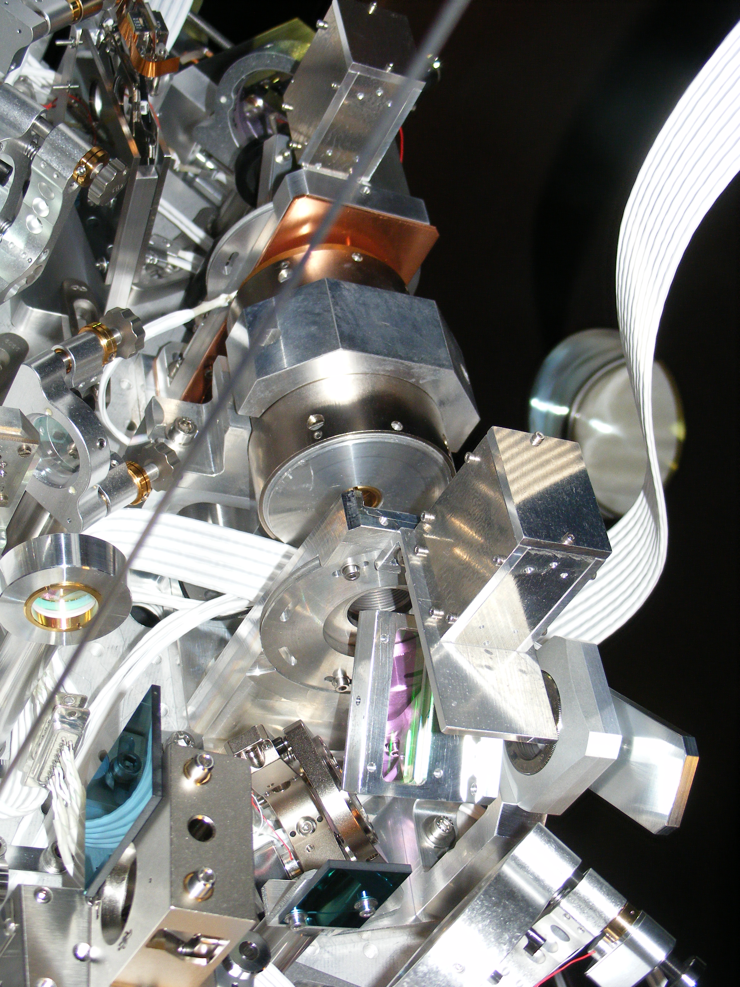
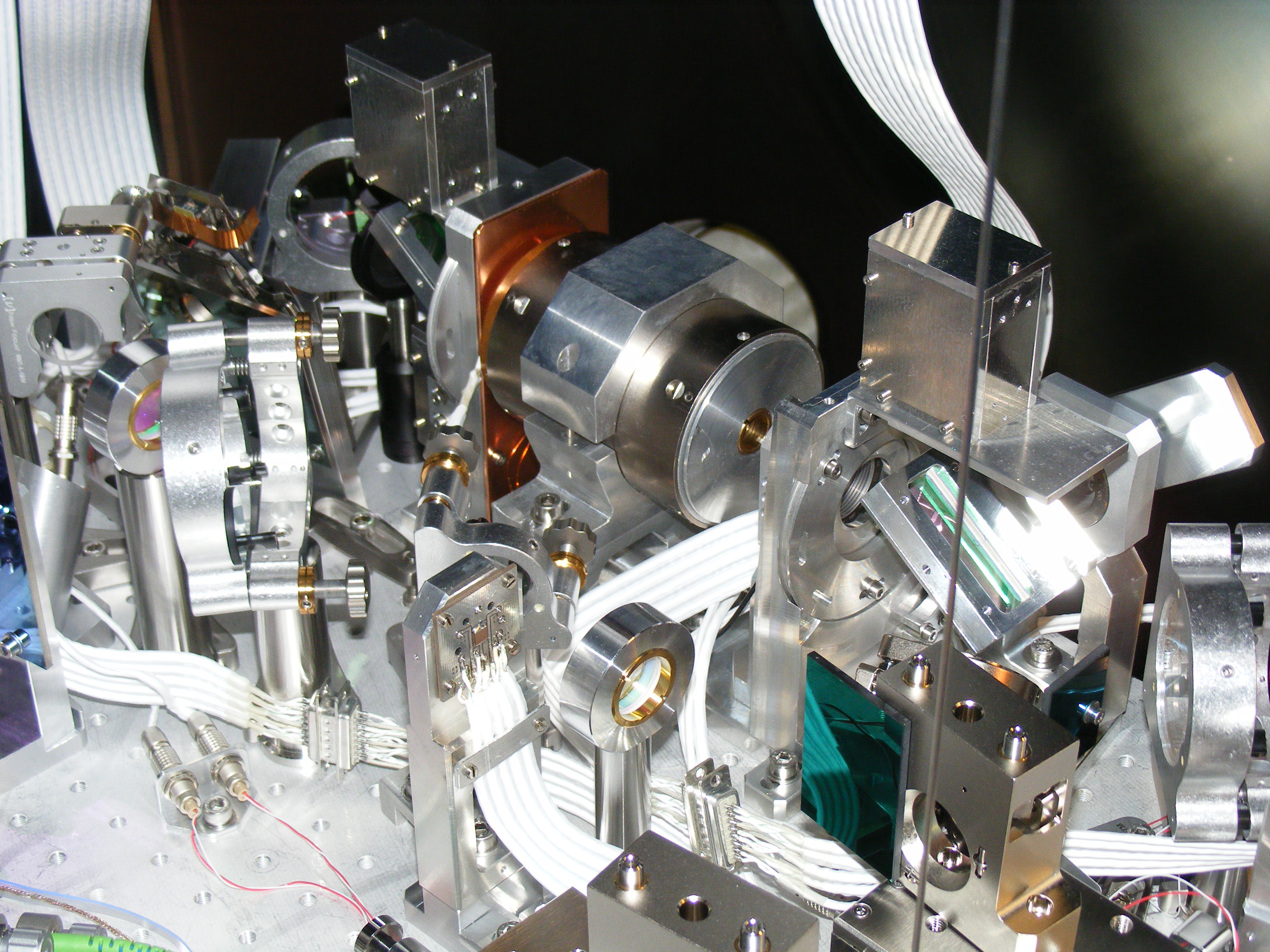
On Tuesday (Feb 13) the old Faraday was dismounted and the new Faraday installed on the bench. A few pictures of the benches once the new FI installed are attached. The in-vacuum cable of the new Faraday (prepared by EGO) was also installed and cabled following the scheme shown in the attached pdf. A few mirror picomotors have been unplugged in order to allow the driving of the Faraday device:
· The Faraday shutter (rotator stage, channel 1 axis 1) has been connected using the twisted pair of the B5_M1_TY picomotor.
· The Faraday waveplate rotator (channel 1 axis 2) has been connected using the twisted pair of the M1_TY picomotor.
· The Faraday Peltier has been connected using the twisted pair of the M1_TX picomotor.
· The Faraday picomotor (TY axis) has been connected using the twisted pair of the MMT_L2_X picomotor.
· The Faraday picomotor (TX axis) has been connected using the twisted pair of the MMT_L2_Y picomotor.
All motors (rotators, picomotors) have been tested after the final cabling and work fine. A preliminary test of the Peltier driving was performed but deserves some further work.
After the substitution of the Faraday, the beam was easily realigned on the references provided by the irises, and the residual light reflected by the Faraday was found on the external squeezer (SQZ) bench.
On Wednesday we also a motorized wave plate in front of the OMC and then dismounted the reference laser setup from SDB1. We then proceeded to the rebalancing of the bench. We removed 1808 g of counter-weights in order to compensate the extra weight of 1843 g added after the installation of the new Faraday and waveplate. Therefore the bench weight should have remained constant within a few tens of grammes. After moving a few counter weights to recover a correct balancing the bench and suspension controls were closed without problem.
The beam coming from the direct bounce on the NI mirror was then used in order to recheck the alignment on SDB1 and on SDB2. It was again checked that the beam reflected by the Faraday was arriving on the external squeezer bench.
The polarization of the beam arriving on the External SQZ bench has been checked with a polarizer mounted in a rotation stage. This will be used to adjust the double stage FI polarizers.