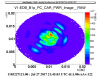
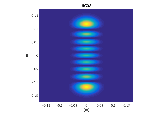
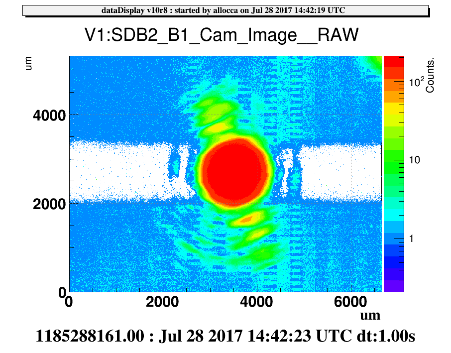
Looking at the dark fringe on the B1p camera, it is possible to recognize a HOM of order 8. In figure 1 there is an image taken with the PC on B1p. The central area of the plot is brighter because of the gaussian contribution due to the darm offset, while on a diagonal row it is possible to recognize a HG08, which is shown in figure 2 (this is just a simulation of the HG08, to better show the shape).
To understand where it comes from, a quick simulation in Finesse has been performed in order to see where the resonance of the order 8 modes fall in the FSR. In this simulation the cold values of the RoCs have been used (ROC_NE = 1695 m, ROC_WE = 1696 m) and not the nominal ones (ROC_ETM = 1683 m), but it will be worth to vary them a bit in order to account for the thermoelastic deformation due to the YAG heating. However, for the current heating the Gouy phase shouldn't be so different.
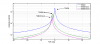
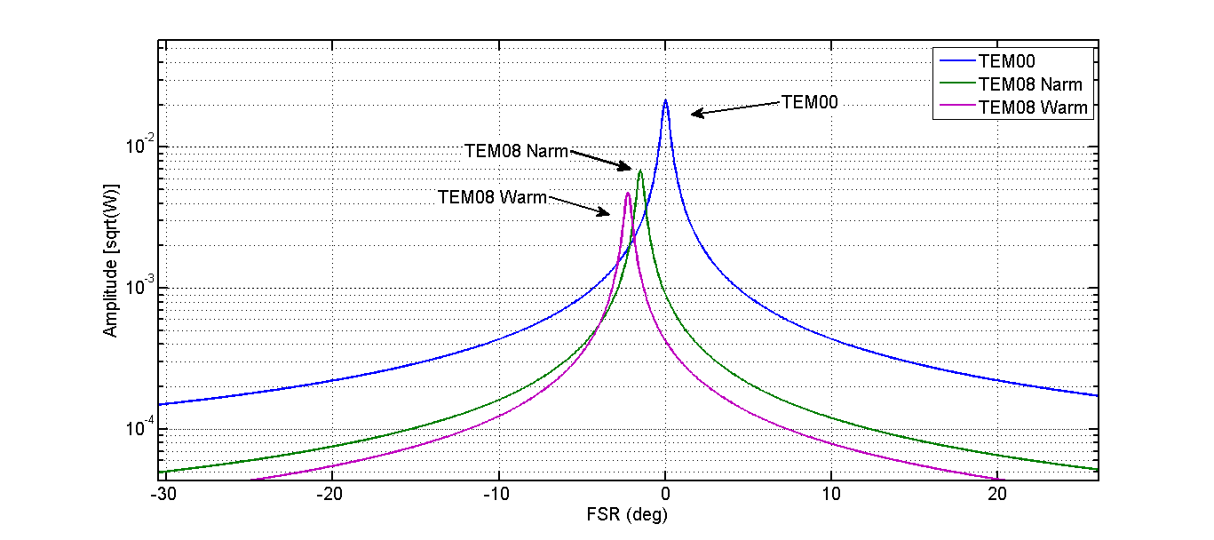
In figure 3 a zoom of the FSR around the TEM00 mode is shown, and very close to its resonance it is possible to see the HG08 resonance for both the North and the West arms. Because of the slight difference in the RoCs, the situation of the North arm is a bit worse with respect to the West arm one. Notice that in this simulation one should only consider the position in the FSR and not the amplitude of the HG08 mode, since the amplitude depends also on the percentage of HG08 added to the input beam in the simulation.
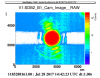
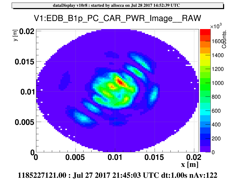
This seems to suggest that a small fraction of the HG08 mode is put into resonance in the arm cavities. This seems also to be confirmed by the fact that a small fraction of the HG08 mode also passes through also the two OMCs (see figure 4), which means that this mode resonates at the same frequency as the TEM00 mode.
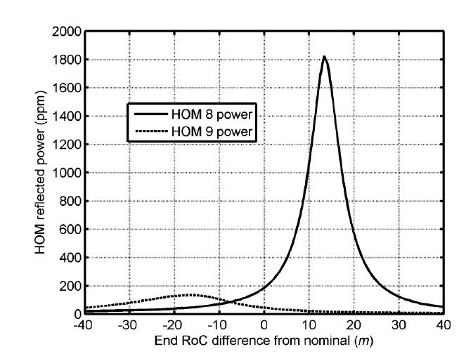
This was actually already computed and reported in the CHRAC paper, from where I took the plot reported in figure 5. The cold radius of curvature of the currently installed End mirror is ~15m bigger than the nominal, so we fall in the area of the plot where the order 8 mode is put into resonance. However, this plot cannot be taken completely into account since it was produced using 1420m (nominal) as RoC for the ITMs instead of 1424.6m (cold, installed).
For the moment, we are not limited by the losses asymmetry, so this mode doe not represent a problem, but it is could start limit us in the future for higher input power for instance. At that point, we should consider the possibility of varying the ETM RoC to move that mode away from resonance.

