today the TCS Team attempted to drive the Flip Mirrors they use on the CO2 benches.
To flip, they need to receive a TTL signal on their "TTL IN" input.
At this time, this input is driven through a bipolar DAC channel (LAPP's).
We have run into a couple of weird phenomena, previously unheard of, while trying to understand the difficulties found when trying to use the system.
First of all, there seems to be a intermittent contact between the flipper body (electrical ground) connection and the optical bench which, in turn, causes the driving channel to divide by two its output signal at times, likely due to the grounding of the negative leg of the DAC's line driver output stage.
The second one, more surprising, is that apparently the TTL In needs to be *negative* for the whole thing to do what it is supposed to. And no, it is not a problem due to cabling.
Probably the wisest course of action is to use a Digital Output module to drive TTL inputs.
CO2 benches - Flip Mirrors --part 2
Further investigation on this admittedly minor but nevertheless puzzling issue have allowed us to dig out the following information:
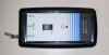
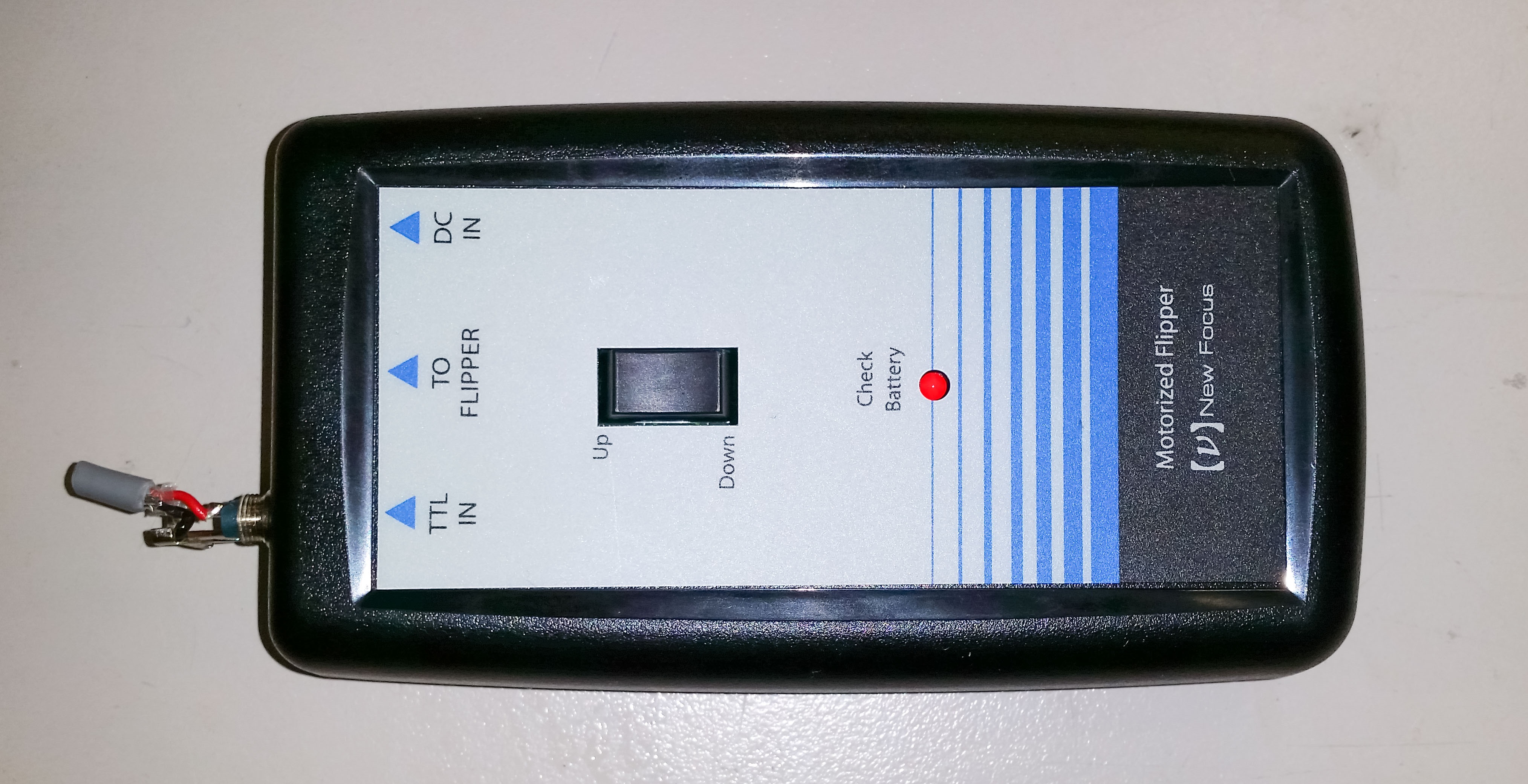
1. the flipper Handpad (fig.1) bought from New Focus for AdV are slightly different from the ones which were bought for Virgo: they have two connectors, one for Power In and one for TTL In, that look exactly the same but are of different size.
Virgo + TTL In 2.1-mm socket Power In 2.5-mm socket
AdV TTL In 2.5-mm socket Power In 2.1-mm socket
They have therefore been swapped (!)
2. The cables made for AdV are an exact copy of the ones made for Virgo+. A sample of the latter is visible in the previous figure (red wire - central contact, black wire - connector body)
3. the datasheet we found, that should refer to the latest version of the handpad, since they state that the bigger connector is the one for the TTL input, report that the positive contact for the TTL signal is the body of the connector, fig. 2. Incidentally, there are mistakes on this page, which give us pause especially when confronted with contradicting information
We then conclude that either in Virgo the "negative TTL" existed but people dealing with the system experimentally found out that including a minus sign somewhere worked and never thought about it twice (no trace in the logbook) or the perverted change in connector size was coupled with an even meaner inversion of polarity.
As for the flimsy ground connection and its effect on the driving voltage level, it is probably worth noticing that in the past the DAC channels used (improperly) to drive logic inputs were truly differential, meaning that they did not know or care where their reference ground level was and therefore there was no problem at all shorting their "negative" side to ground.
In AdV, with the topology adopted for the output stage of all DAC we know of, this is not longer possible without collateral effects on the DAC Channel itself.
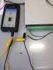
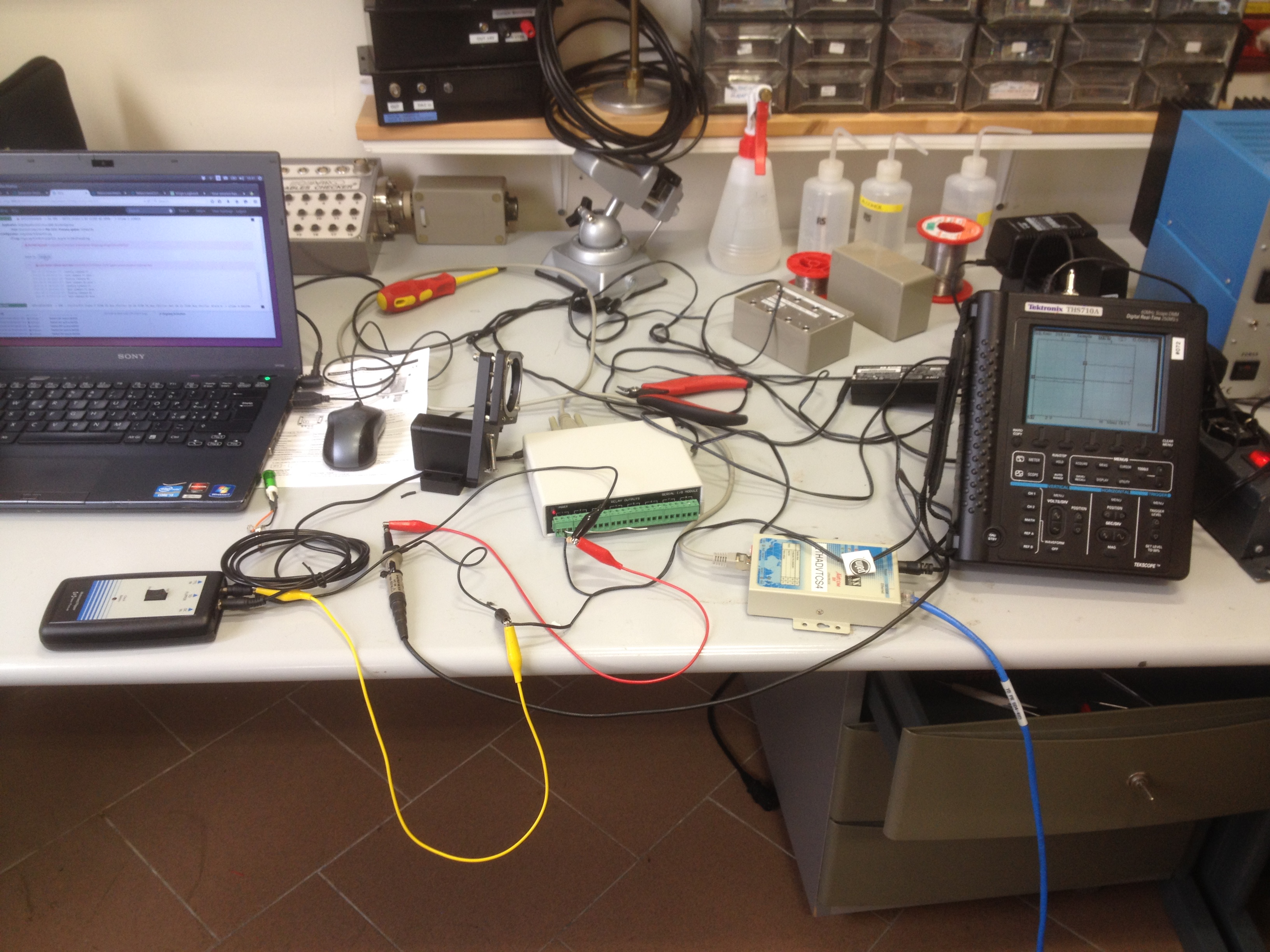
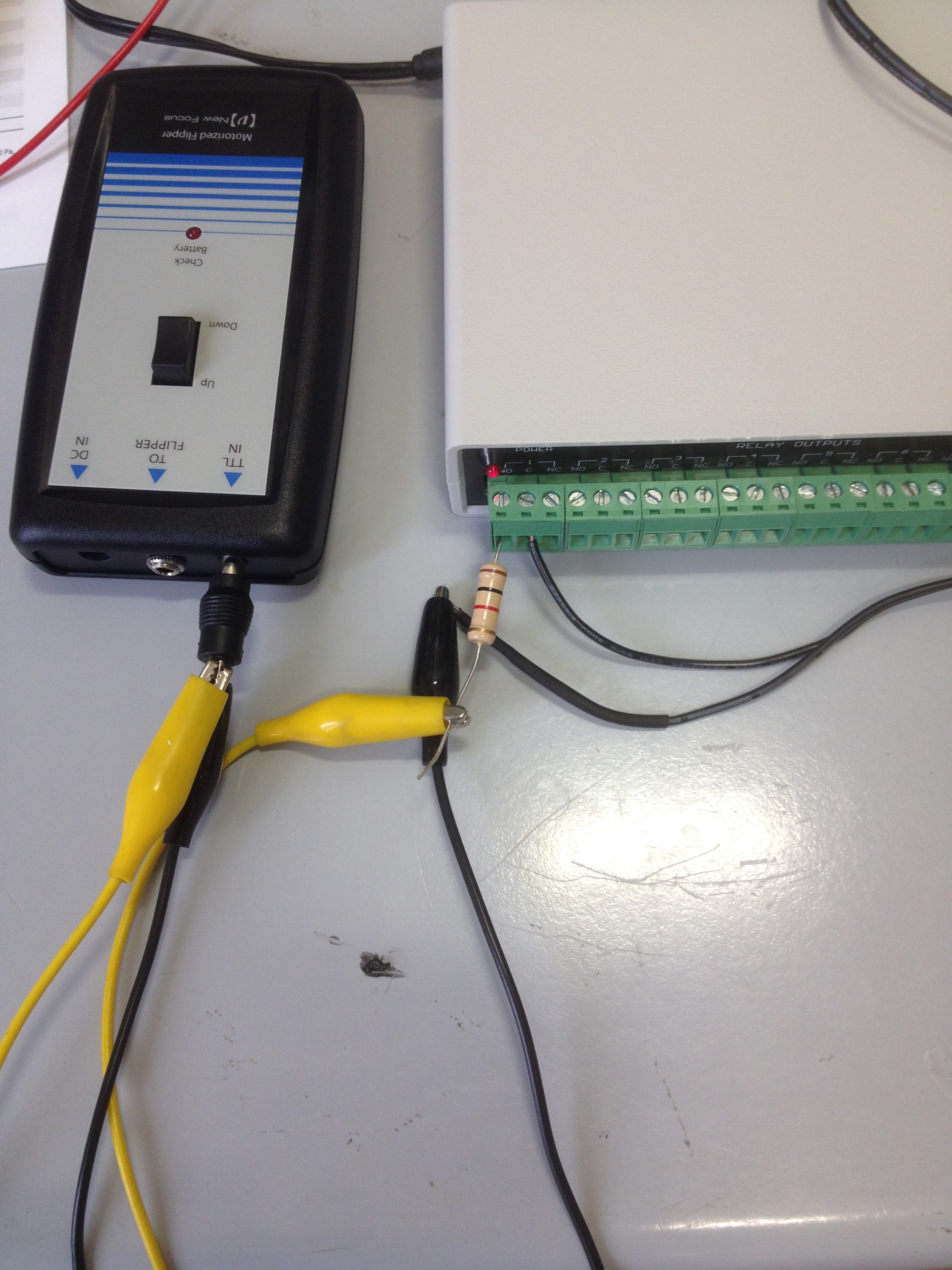
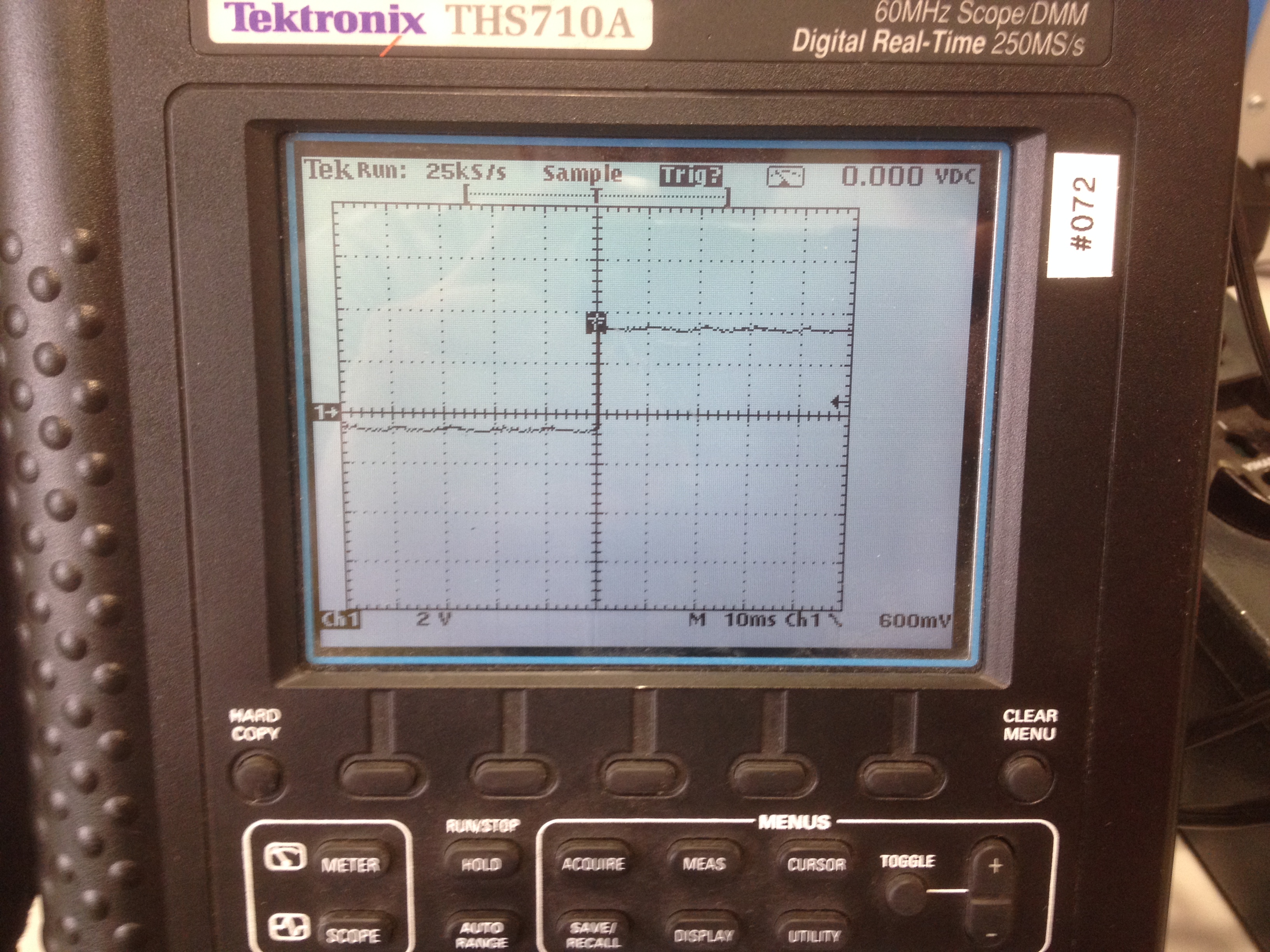
In order to check that the electrical configuration would be correct (in particular for the CO2 lasers which TTL input has created problem in the past) a test setup has been made in the Electronic lab (Fig. 1) using a standard power supply connected to the TTL input of a flipper driver via the switchbox (Fig. 2).
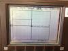
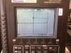
All seen DC levels were correct and during both transients the waveforms were as expected without presence of spikes or over/undershoots (Fig 3-4). We also checked that the use of a 1K resistor in series to the TTL input makes a little difference.
Out of those tests it seems the switchboxes (drivable via the already available Ethernet/Serial bridges and dedicated software Sb) are a suitable solution for commanding the flippers and the CO2 lasers power on/off.

CO2 benches - Flip Mirrors --part 3
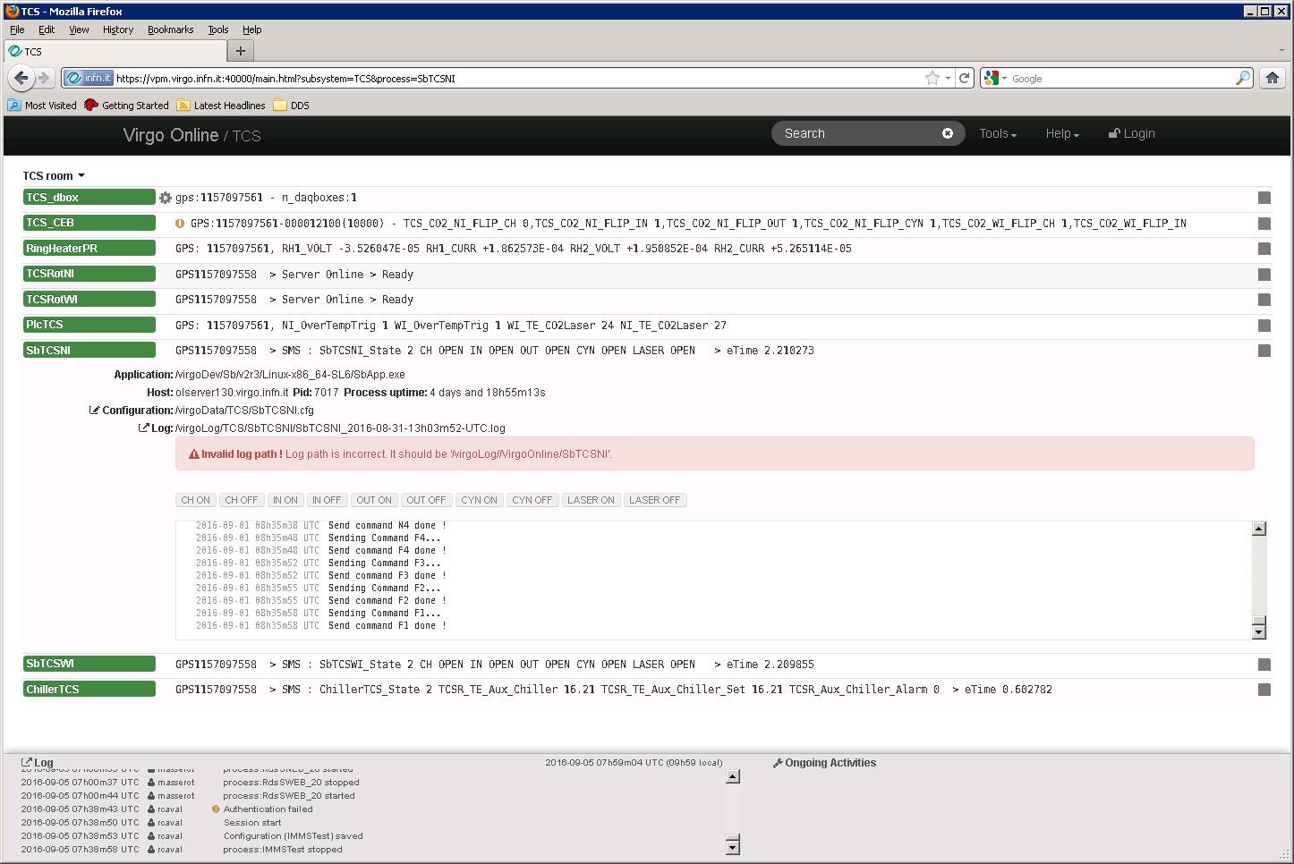
All Flip Mirrors on CO2 benches can be now controlled independently through an interface available in the VPM (TCS/SbTCSNI for North Input Bench and TCS/SbTCSWI for West Input Bench).
There are four flip mirrors on each bench, named Central Heating (CH), INner Ring of DAS (IN), OUTer Ring of DAS (OUT), CYNogy Camera (CYN) --the latter is misspelled, it is actually a Cinogy camera.
On the interface there are two push buttons for each mirror, ChannelName ON and ChannelName OFF (i.e., CH ON and CH OFF and so on).
The convention is that the button actions are referred to the beam along which the flip mirrors are placed: CH ON means that when in this position the mirror does *not* stop the Central Heating beam (i.e., the Central Heating is "active"). CH OFF means, of course, the opposite (the Central Heating beam is blocked).
The coexistence of the manual and remote actuation, as it is, has few shortcomings:
1. The position selected through the VPM interface is "knowable": a text line at the very top of the relative VPM page tells whether a given switch is OPEN (=0) or CLOSE (=1).
The same info is visible in DataDisplay.
The actions through the Flipper's Handpad are not traceable though. Therefore, the actual position of the mirror is, a priori, not known with absolute certainty, at least directly (it could be deduced indirectly in some other way, for example using beam pickoff's info, for example).
The info available on the VPM interface can therefore be out of sync with the real position of the mirror.
2. the datasheet of the Handpad states that "the handpad switch overrides the TTL input". That is misleading. Reality is that
is the temporal sequence of issued commands that counts, no matter if they are issued remotely or via the handpad.
If the last command is a transition low->high (0V->5V, or equivalently ON->OFF) then the mirror in question will be placed on the beam path.
This implies that no matter what the status switch says (OPEN or CLOSE), if with your next command you want to make sure to bring the switch in the status currently displayed, you have to do a complete cycle (2 transitions). If instead you just want to go in the other state a single transition (i.e., one button push) is sufficient.
In both cases you will bring actual position and status indicator back on sync.
Points 1 and 2 above could be solved in different ways (at a price, of course); for example,
(a) we get rid of the possibility to move the mirrors by remote command
(b) we use a more complex system that cannot, by design, be out of sync
(c) whoever uses the handpad puts back the mirror in the position where it was before he/she started
(d) nobody uses the handpad anymore (or better still we remove the lever that allows to use it)
3. Other (potential) weaknesses of the present remote control implementation (such as immunity to glitches due to things like combination of minimum recovery time after a commutation and sensitivity to fronts instead of levels, grounding issues...) aimed at addressing reported malfunctions will be investigated and the results will be reported here when somehow conclusive.
- Any reference to the Flip mirrors has been removed / commented out on the TCS_CEB process configuration file
- On the VPM configuration:
. the commanding of Flip Mirrors from TCS_CEB has been removed
. two instances (SbTCSNI, SbTCSWI) of the Sb process has been introduced
. the commanding of Flip Mirrors from SbTCSNI and SbTCSWI has been added as specified in the entry
- SMS data acquisition from SbTCSNI and SbTCSWI has been added in the FbsAlp configuration