Today, after Michal noticed that the B1 beam was not properly centered on the B1 PD2 photodiode (logbook entry 44486), we investigated this issue, first by trying the recenter the beam with picomotors, by scanning the angular position of the SDB2 bench, and also by playing with the BS TY setpoint. The maximum power that could be reached on this photodiode was only a third of the expected level (that could be deduced from B1s2 when the OMC2 was out of resonance). Moreover during the angular scan of SDB2, we could not observe any plateau on this photodiode. This suggested that the beam was clipped somewhere (on the photodiode or on a mount).
Thus we decided to open the SDB2 minitower in order to inspect the bench for a possible clipping along the B1 beam path. Finally we noticed that one of the pawls of the B1_M2 mount that is normally used to hold the 2 inch optics was not properly positioned and did not seem in contact with the HR mirror. After repositioning correctly this pawl against the mirror, it was immediately possible to recover the expected level of power on the B1 PD2 photodiode.
The conclusion is that the miscentering of the beam on the B1 PD2 photodiode was due to a misalignment of the HR mirror which was not correctly mounted during last week intervention (logbook 44458). A lesson that we learn from this mistake is that such kind of operation (replacement of optics on a suspended bench) should be done with a beam available in order to have the chance to check for the correct alignment of the manipulated optics.
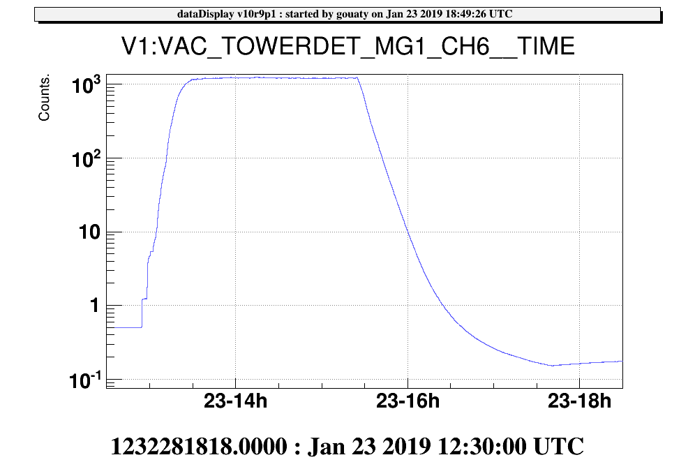
The minitower venting started around 13h00 utc. The pumping was started at about 15h20 utc (see Fig.1). Alessandro could restore the control of the suspensions towards 16h20 utc.
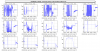
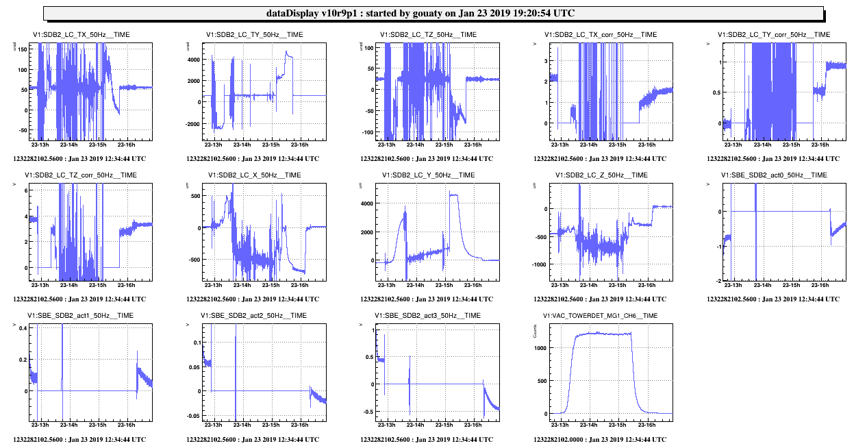
Unfortunately the torque of the suspension wire seems to have increased, as the correction signal in TY has increased by almost 1V (see Fig.2) after the suspension loops were closed. One can also notice that the bench moved by about 500 um in Z.
After the SDB2 intervention, Michal adjusted the relative alignment between OMC1 and OMC2 using the single bounce beam from NI aligned. During this operation both OMC cavities were locked (more details to come in a dedicated entry).