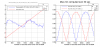
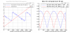
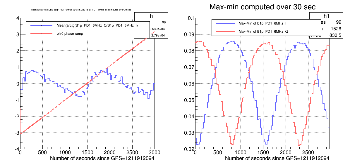
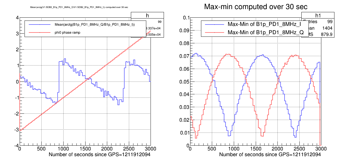
Fomr GPS=1211912094 to GPS=1211915094, with the ITF in free short michelson configuration, we have performed a ramp of the phase offsets SDB2_B1p_6MHz_phi0 and SDB2_B1p_8MHz_phi0 in order to study the best way to determine automatically, before each FREEMICH calibration, the value of phi0 which maximizes the signal SDB2_B1p_PD1_{6,8}MHz_I and minimizes the signal SDB2_B1p_PD1_(6,8)MHz_Q.
The ramp was from -pi to +pi with a step of 2*pi/100 every 30 sec.
Plots 1 and 2 show, for the 6MHz and 8 MHz signals, the value PHI = Mean(arctg(Q-mean(Q)/I-mean(I))) computed over 30 sec (left plot) and the range of the signals I and Q (right plot) during this phi0 ramp.
First conclusion is that the value PHI gives the phase offset to be applied in order to get the largest range on I.
But, for the 6 MHz signals, if PHI is around zero, there is an ambiguity and we need to know the sign of the slope of PHI versus phi0 in the ramp to separate the cases "I range is maximum" and "Q range is maximum".
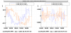
Plot 3 shows the I and Q signals resampled at 0.03 Hz and shows that there is a permanent offset on the signal SDB2_B1p_PD1_6MHz signals which is not present in the 8 MHz signals. The 6MHz signals seem contaminated by some noise that makes its mean value depend on the phi0 used.
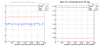
Plot 4 shows that the PHI formula works also for the 56MHz signals (where no phi0 ramp was done). We can check on this plot that the phase offset currently used is the correct one.:B1p_56MHz_phi0 is around 1.2 rad and PHI is around 0 and the range of the I signal is maximum with respect to range of Q signal.
PHI formula will be implemented in CALI METATRON soon. But it would be worth to understand what makes the difference between the B1p_PD1_6MHz and the B1p_PD1_8MHz signals