Figure 1 shows a scan after the alignment, with 8mW on the TEM00, and 80uW on the order 1 modes (at 36m50), note that the TEM00 tail is about 30uW, so the misalignment mode is less than 1%. The order 2 mode (at 37m15) has 300uW so about 4%, and looks like at TEM20 mode (3 spots horizontally aligned), so astigmatism should be the dominant contribution not mode mismatch (which would give a doughnut shaped image).
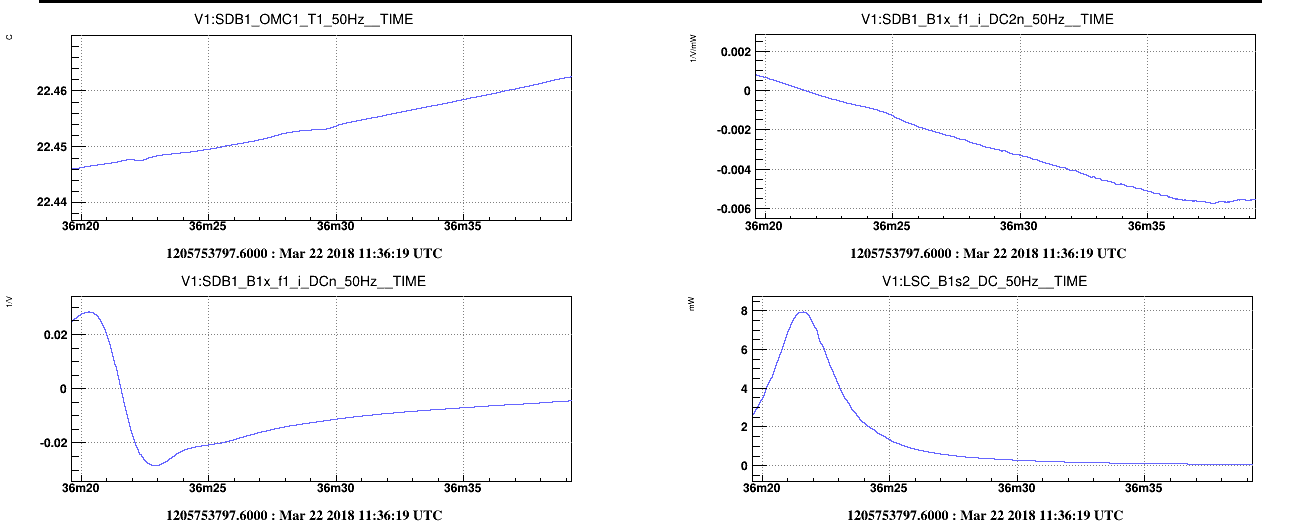
Added a new normalization for the OMC error signal. Instead of dividing the demodulated signal by the DC power (and the amplitude of the modulation) (f1_i_DCn), dividing by the DC power squared (f1_i_DC2n). From the derivation of an Airy peak this normalization by DC squared should be linear on a much wider range. On figure 3, clearly the linear range of the signal has a dynamic that is about 10 times larger, it breaks down when other peaks that the TEM00 are not negligible anymore (here the TEM10 starts to raise above the TEM00 tail).
Between 12:03 UTC and 12:41 UTC did a noise injection into the OMC1 Peltier while the OMC was locked using the Peltier cells only on the new error signal. In parallel allignment on PDs and cameras in reflexion and transsmission was performed.
The lock filter was 3 simple zeros at 0.5, 5 and 10mHz, 2 simple poles at 0Hz and one pole at 50mHz.
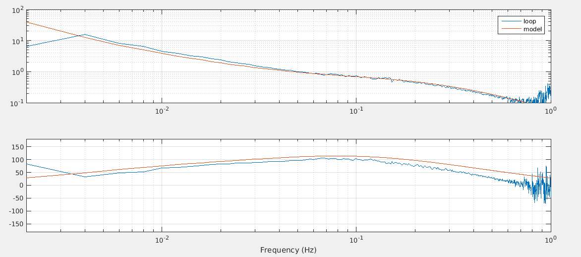
Figure 2 shows in blue the measured open loop transfer function, in red is a model of the loop by including the control filter plus the following for the response:
simple poles at 0.5mHz, 10mHz, 200mHz and 500mHz
simple zeros at 50mHz and 50mHz
not a perfect fit but should be enough to improve the locking filter.