The goal of the shift was to:
1. check with the SR780 spectrum analyser the ultimate performances of the Pstab loop
2. swap the set of Phd1&2 (named PD1) with Phd 3&4 (named PD2) of the Pstab optics box to check that both configurations are equivalent in term of performances and therefore demonstrate that each Phd set could act as the spare of each other.
3. check that both pstab electronics are working (test the spare rampeauto crate).
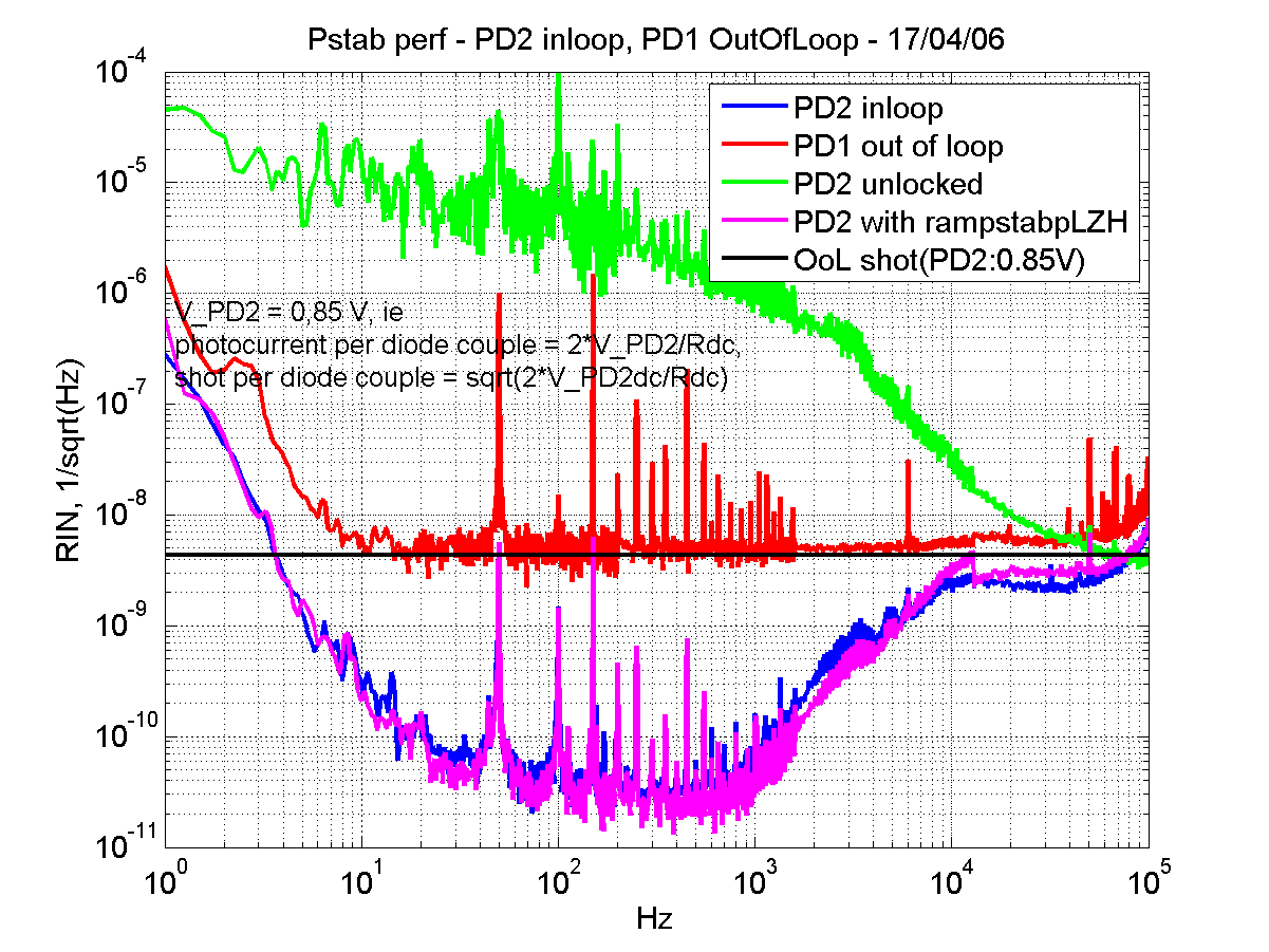
# First plot shows the RIN @ inloop (PD2), OutOfLoop (PD1)
- The green curve is the RIN of the free-running laser.
- The blue one is the RIN at the in-loop photodiode group (PD2 in this case).
- The red curve the RIN at the out-of loop photodiode group (PD1).
- The black curve is the expected shot noise at the OoL Phd for V_PD2 = 0.8567 Volt <-> 17 mA (1); which is the contribution pf both in and OoL Phds.
 We are thus within the specs define in the AdV TDR for wrt the PR ITF@25W (10^-8/sqrt(Hz)).
- The magenta curve is the RIN at the in-loop photodiode group (PD2 in this case) using the spare rampauto. Both rampeautos gains and offsets have been tuned so that swap is easy and in theory nothing should be retuned before reaching the best performances.
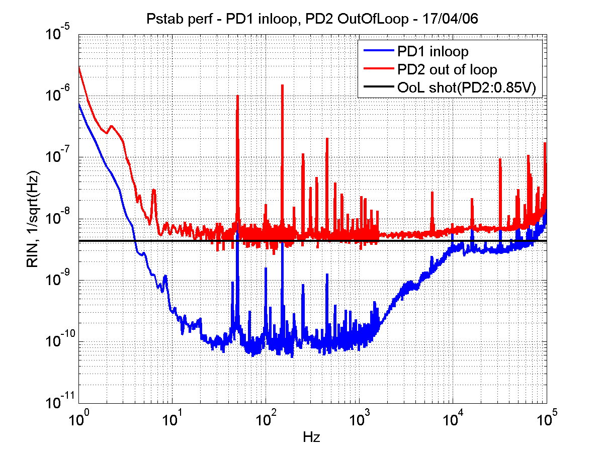
# Second plot shows the RIN @ inloop (PD1), OutOfLoop (PD2): we swap PD1 and PD2 wrt previous plot
(1 ) Note that the so-called "Photodiodes" PD1 and PD2 are a combination of two pairs of photodiodes. PD1 and PD2 are equivalent and can be used as in-loop or out-of-loop sensor
Each pair of photodiodes has its own transimpedance amplifier. The output of both amplifiers are sent in a 2-resistor network, providing the average of their outputs at the common point.
- The contribution of each single photodiode is then multiplied by 0.5.
-> The overall dark/shot noise is the quadratic sum of both individual contribution multiplied by 0.5.
-> The overall photocurrent is the linear sum of both individual contribution multiplied by 0.5.
One must use “2*V_PD2/50†as the contribution to the photocurrent when assessing the shot noise contribution at one photodiode PD1 or PD2 (50 states for the 50 ohms load of the photodiodes preamplifier).
That is RIN_shot = sqrt(2.e. 2*V_PD2/50)/[ 2*V_PD2/50] = 3,05 e-9 /sqrt(Hz).
Please note that the overall noise at the OoL is the quadratic sum of the shot contribution @PD1 and PD2, that is 4,32 e-9 /sqrt(Hz).
In the end, we left the ramstabp rampeauto installed. The spare unit is currently stored in the EEroom.

