First, we implemented the lock acquisition procedure performed yesterday evening: it worked reliably again this morning.
At 07:23 UTC, Manuel gradually increased the injected power up to 17.5 W (INJ_IMC_TRA_DC) in CARM_NULL_1F. The ITF unlocked at 07:53 UTC due to a suspension glitch similar to previous events.
We reacquired CARM_NULL_1F at around 08:11 UTC with an injected power of 17.7 W, closer to the nominal 18 W. The ITF unlocked at 08:27 UTC, as MICH and DARM drifted away without a clear trigger.
Finally, at 08:43 UTC, CARM_NULL_1F was acquired again at 17.8 W of injected power.
At this point, we started the thermal tuning; the initial configuration is reported in 69838.
The plan is to explore the effect of the WI DAS IN power and to perform a differential step. We agreed to double the NI DAS IN injected power and evaluate its effect on the ITF.
08:56 UTC STEP 1
WI DAS IN +100%
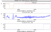
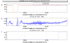
The SBs responded quite rapidly going down and the dark fringe worsened, indicating that increasing the WI DAS IN power is not the correct direction. So we agreed to close the flip mirror of the WI INner DAS.
09:38 UTC STEP 2
WI DAS IN set to 0 (flip mirror closed)
See Fig. 1 for ITF signals corresponding to these two steps.
Since the DAS differential steps did not seem to have a significant impact, Michal suggested performing a differential ETM RH step. In particular, we decreased the WE RoC by acting on the RH, as the strong PA on the WI is expected to induce additional curvature
10.31 UTC STEP 3
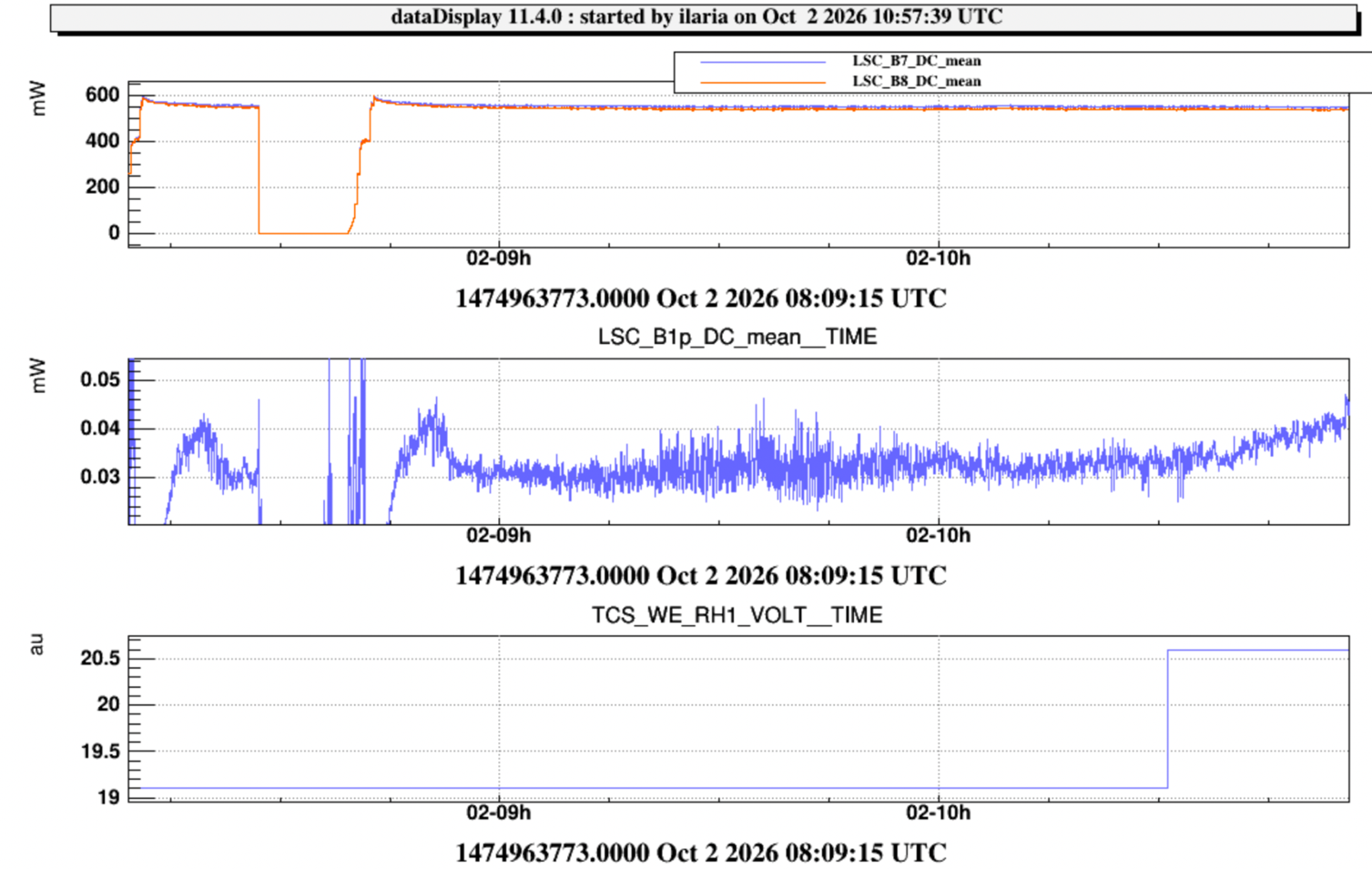
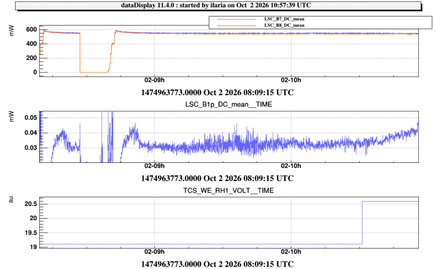
WE RH RoC reduced by 4 m, that is V = 19.1 V → 20.6 V and P = 9.8 W → 11.4 W
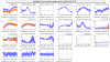
This last step rapidly increased the dark fringe brightness (see Fig. 2), so the step was reversed and then continued in the opposite direction of the same amount.
11.03 UTC STEP 4
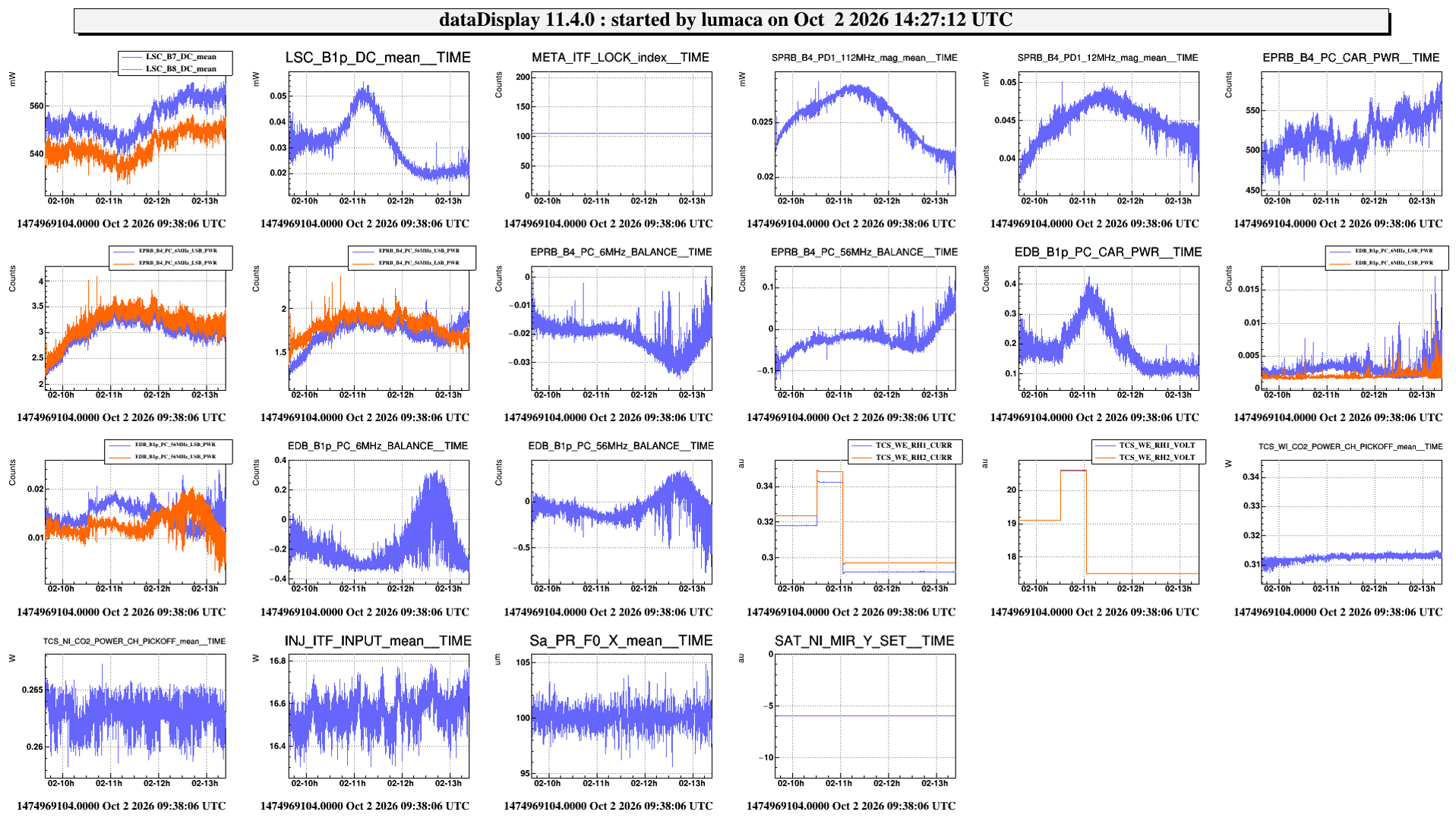
WE RH RoC increased by 8 m, that is V = 20.6 V → 17.5 V and P = 11.4 W → 8.2 W
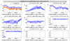
The effect of the last step of WE RH seemed good: B1p decreased up to 0.02 mW (around 12.40 UTC), before restarting to rise up (see fig 3).
13:29 UTC STEP 5
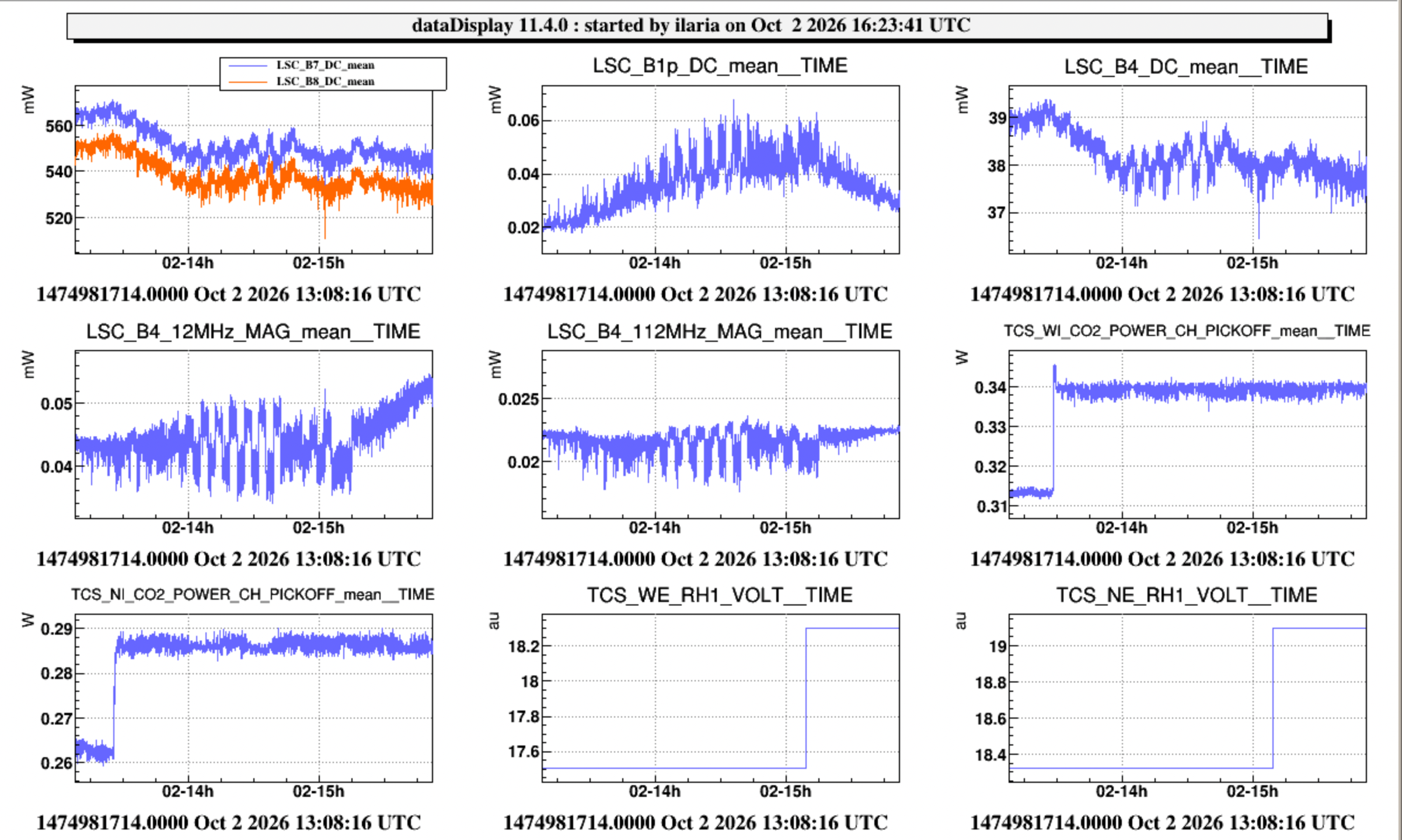
NI DAS IN and OUT +10%
WI DAS OUT +10%
The effect of this last step is ongoing.
The configuration of the CO2 actuators, so far, is summarized in the table below:
|
| CH [W] | INNER DAS [W] | OUTER DAS [W] | |
| WI | on the ITF | 0.070 | 0 | 2.034 |
| on the pickoff | 0.427 | 0 | 0.331 | |
| NI | on the ITF | 0.064 | 0.351 | 1.426 |
| on the pickoff | 0.392 | 0.057 | 0.232 |