This morning we resumed our activities on the SDB2 bench. We reopen the OMC shutter at 07h34 utc. We checked that the bench position (blocked) and the beam position on the B1p, B1s and B5 cameras did not change during the night.
We install one iris on the B1s beam path next to the SDB2-EDB viewport and another iris in front of the OMC to have alignment references.
We start the process of displacing SDB2_B5_M1 to its new position: (x, y) = ( -0.225, -0.331) m (using the optocad reference frame).
We realigned the B1s beam on the first iris by acting on B1s_M2 picomotor:
- B1s_M2_V: 2700
- B1s_M2_H: 13000
We also realign the B1s beam on the iris placed in front of the external OMC by acting on the last folding mirror before the EDB telescope.
We acted on the picomotors of B5_M1 in order to center the beam on B5_QD1.
- B5_M1_H: -3800
- B5_M1_V: -6000
To characterize the beam after the lens, we use the Smartek camera, its sensor is placed at an initial position (z=0) which corresponds to the bench coordinate X=-450+22.5-12 = -439.5mm along the beam axis between the galvo and the quadrant.
We take data points at:
- z=0 at 14h37 utc (integration time is set to 8000 us)
- z=25 at 14h42 utc
- z=50 at 14h46 utc
- z=75 at 14h51 utc
- z=100 at 14h52 utc
- z=125 at 14h55 utc
##### Error in measurement: height of beam on the lens was mistakenly changed
- z=275 at 15h13 utc (we change the integration time to 16000 us)
- z=300 at 15h16 utc
- z=325 at 15h19 utc
- z=350 at 15h22 utc
- z=375 at 15h24 utc
- z=400 at 15h26 utc
##### New measurements with corrected height of beam on the lens
- z=275 at 15h37 utc (we change the integration time to 16000 us)
- z=300 at 15h43 utc
- z=325 at 15h46 utc
- z=350 at 15h49 utc
- z=375 at 15h52 utc
- z=400 at 15h55 utc
- z=425 at 15h58 utc
- z=450 at 16h01 utc
- z=475 at 16h05 utc
The analysis of these data points gives the following parameters for the B1s beam going towards the quadrant:
* Sagital beam : w0s = 322.3 +/-2.3 um, z0s = -116.8 +/-2.3 mm, zRs = 306.7 mm
* Tangential beam : w0t = 256.7 +/-1 um, z0t = -68.9 +/-1.3 mm, zRt = 194.6 mm
This gives the following coordinates for the Gouy phase at 45 deg:
* For the sagital axis (vertical), X = -439.5 + z0S +zRS = -249.6mm
* For the tangential axis (horizontal), X = -439.5 + z0t +zRt = - 313.8 mm
Therefore the QPD sensor should be placed around X = -281.7 mm. This means that the QPD oblong hole should be around X = -258.2. Since this position is too close from the galvo, we displaced the galvo by -75 mm in Y in order to shorten the optical path. And we finally placed the QPD sensor at X=-350-23.5 = -373.5 mm, and Y = 450 mm.
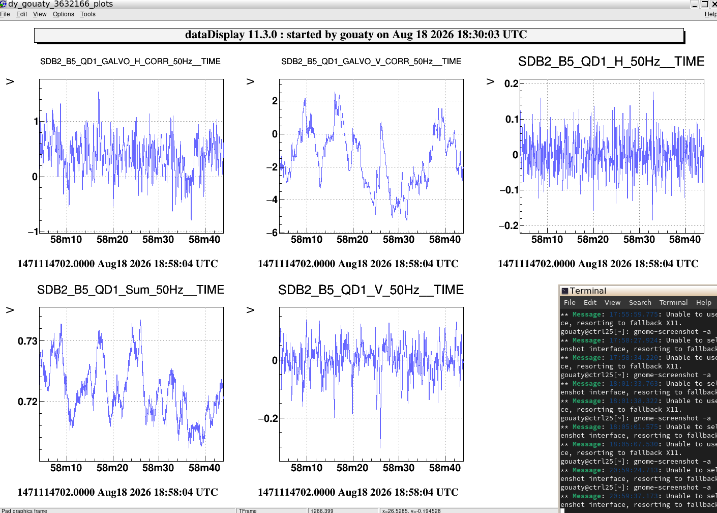
We then aligned the beam on the QPD by acting on the B5_M1 picomotors with -3800 steps in H and +2800 steps in V. We then were able to close the galvo loops as shown on Fig.1. We notice that the corrections in vertical have large fluctuations. This is probably due to the limited distance between the galvo and the quadrant (only ~123 mm).
We added a beam dump in reflection of the QPD.
During this process we had to remove and add some components, namely:
- Removed: Beam dump and screws weighing 169g.
- Added: clamp weighing 20g
- Added: 5 cable ties weighing 6.5g
- Added: cable extension weighing 42g
- Added: clamp and screws weighing 23g
- Added: new lens (f = 125 mm) mounted on column and clamp weighing 267g
- Removed: clamp plus screws weighing 15 g.
- Removed: beam dump in reflection of B5_M1 with clamp and screws weighing 169 g.
- Removed: clamp plus screws weighing 16 g.
- Added: Beam dump and screws weighing 170g (in reflection of the B5_QD1 quadrant).
We stop here for the day. Tomorrow morning we will rebalance the bench and check the alignment with the bench suspended in air.