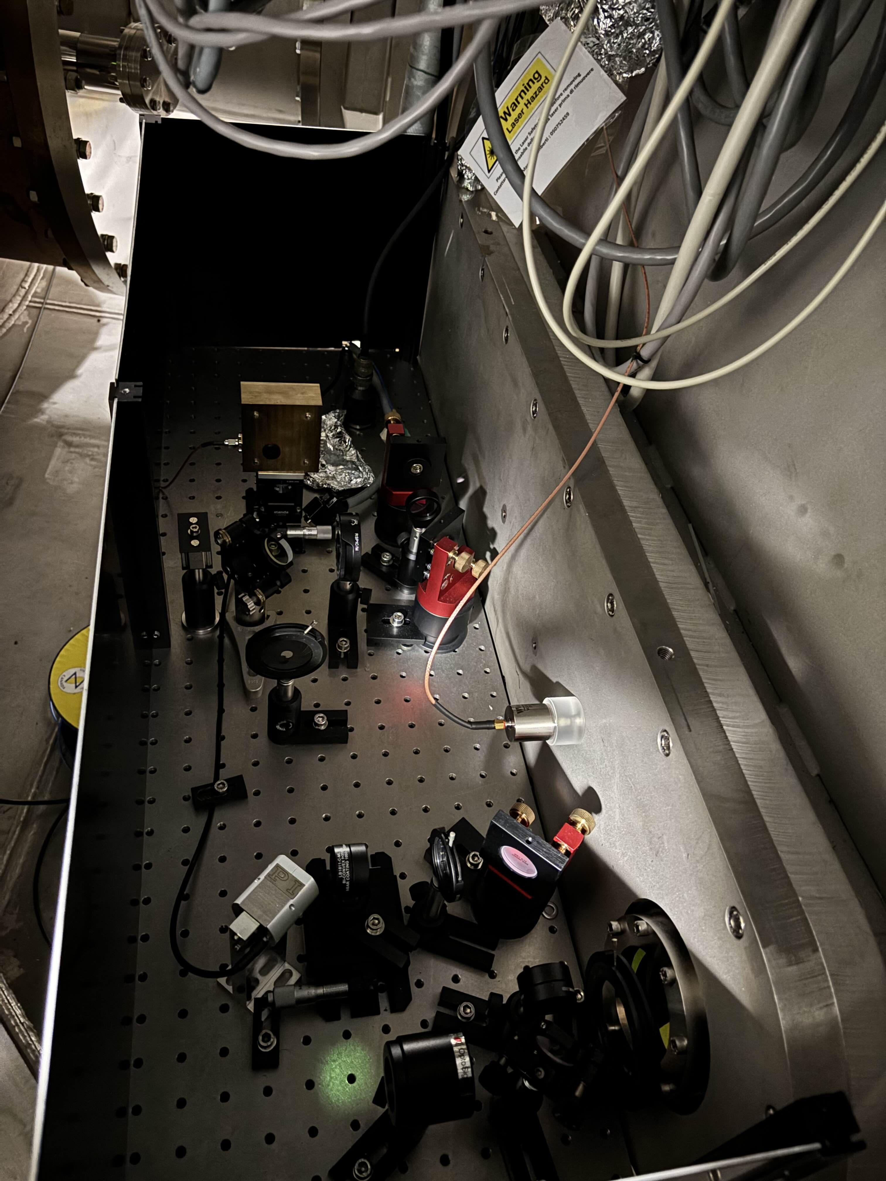
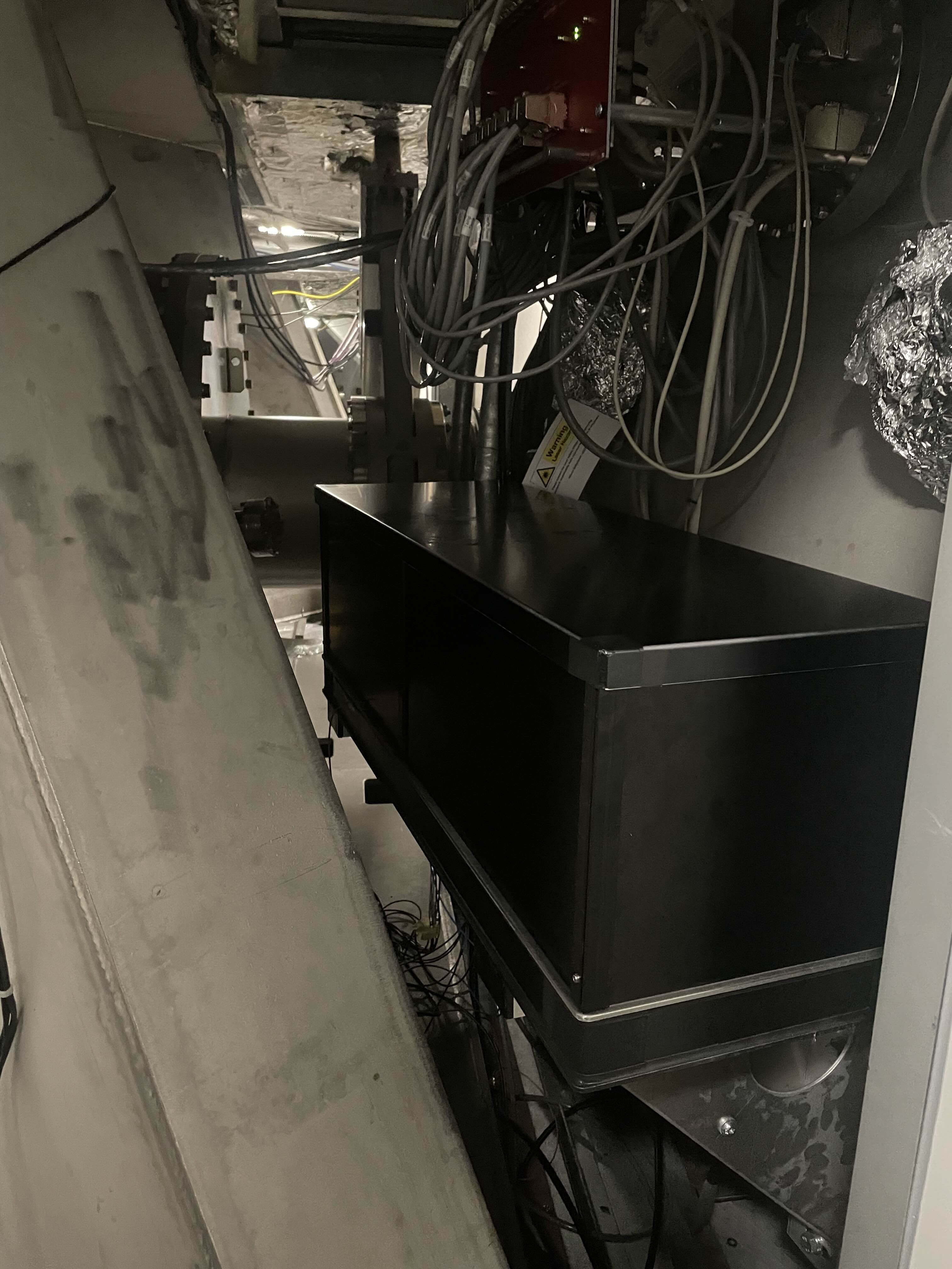
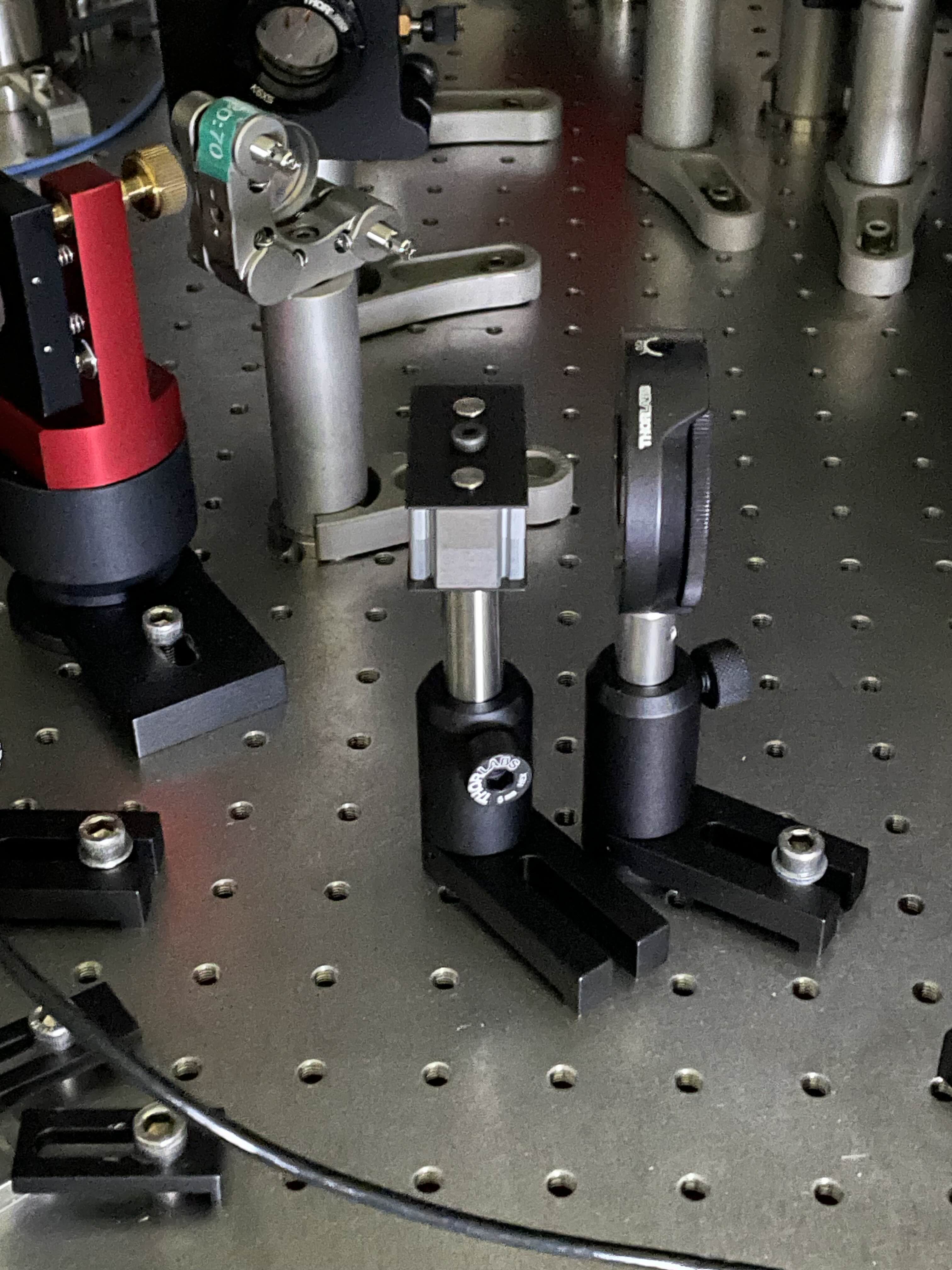
We checked the alignment of both B4 and B1p phase cameras profiting of the interferometer locked with MICH at half fringe.
Work for B4 phase camera:
- at first we removed the scanning FP and its auxiliary optics since it has not benn used for a long time (scanning FP and photodiode have been stored by Suzanne);
- then we checked the superposition of the reference and the B4 beams: even if the power on B4 is not too high, we were able to optimize the superposition between the two beams. We had to remove the neutral densities on the reference beam path since the coupling of the pick-off beam into the oprical fiber in the laser bench is good but not yet optimized (see entry 69572);
- we barely centered the photodiode and we are happy for the time being;
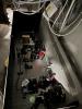
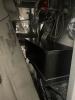
- we added a new cover on the bench to sheld the laser beam (see pictures 1 and 2).
Work for B1p phase camera:
- we checked the superposition of the reference and the B1p beams and it was already almost good;
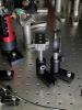
- as requested by Romain, we add a beam dump on the reference beam path for the SDB1 intervention scheduled for next week (see picture 3).
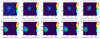
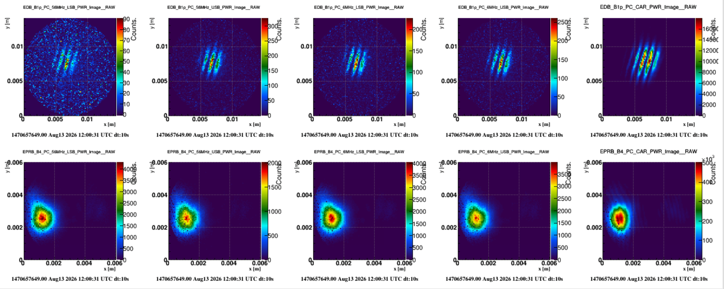
Figure 4 shows the beams acquired by the phase cameras after the intervention: B4 is not perfectly centered, we will optimize its alignment once all the alignment loops are engaged in CARM NULL; B1p is showing fringes, we checkd the path of the beam on the bench and we realized that the fringes are coming from the ITF, probably due to some clipping on the suspended benches not perfectly aligned at this stages.
Next steps:
- Remove the beam dump fon the B1p path after the SDB1 intervention;
- Together with INJ people, optimize the coupling into the fiber on the laser bench for the reference beam. Don't do it before installing back neutral densities on EPRB to avoid to burn the photodiode;
- Optimize the superposition of the beams and the alignment of the photodiodes once the alignment loops are engaged in CARM NULL.