Reports 1-1 of 1 Clear search Modify search
AdV-TCS (CO2 laser projector)
zaza, dattilo, menzione, ciardelli, cavalieri, nardecchia - 11:49 Thursday 06 August 2026 (69506) Print this report
TCS AuxCooling System Upgrade - Elements and Channels

The assembly of the new cooling system for the TCS auxiliary lasers is complete.

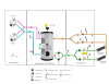
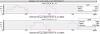
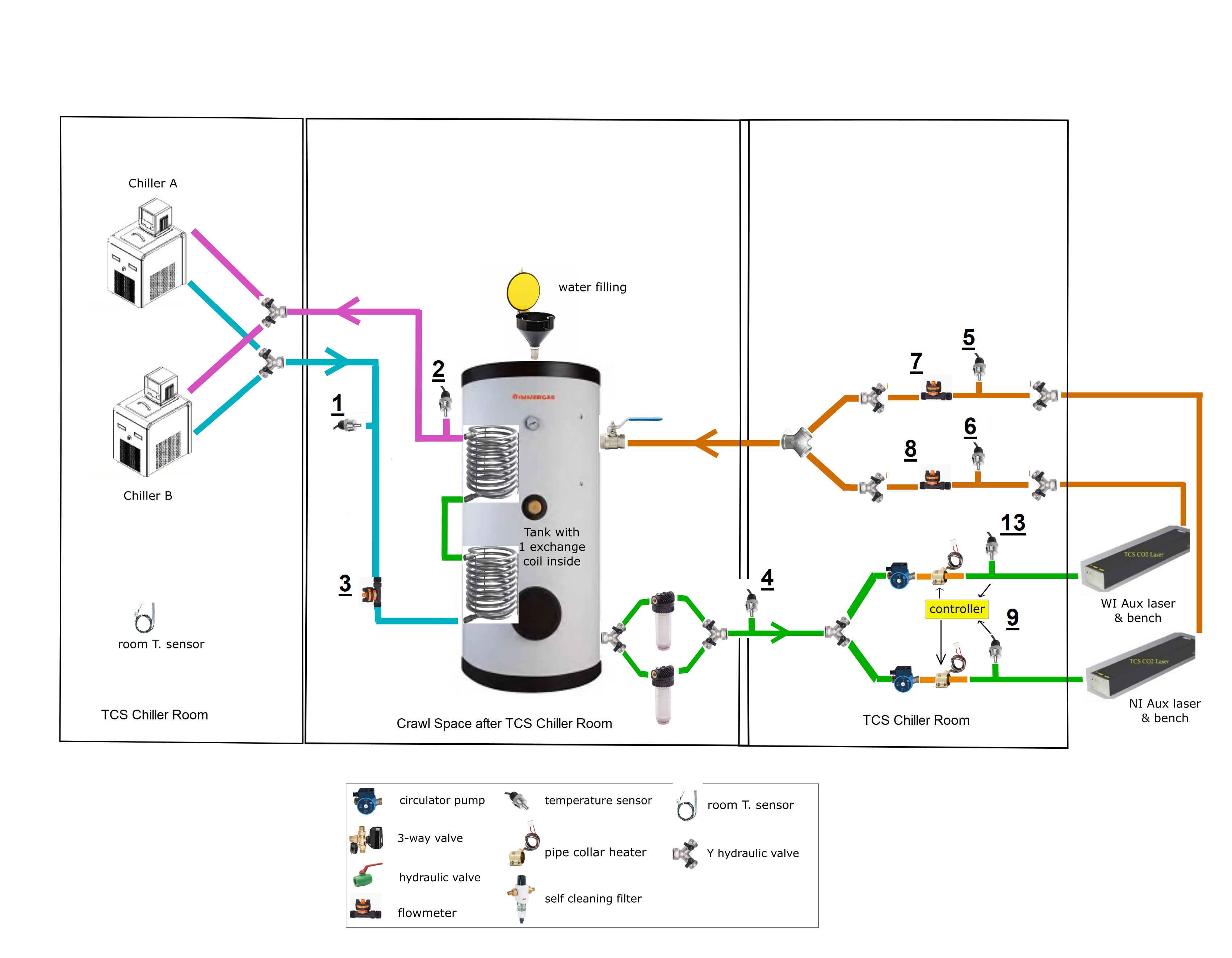
It is a two-stage system (pic 1 - schematics)
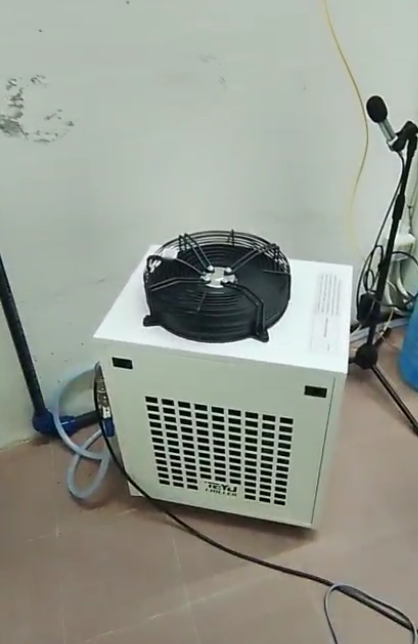
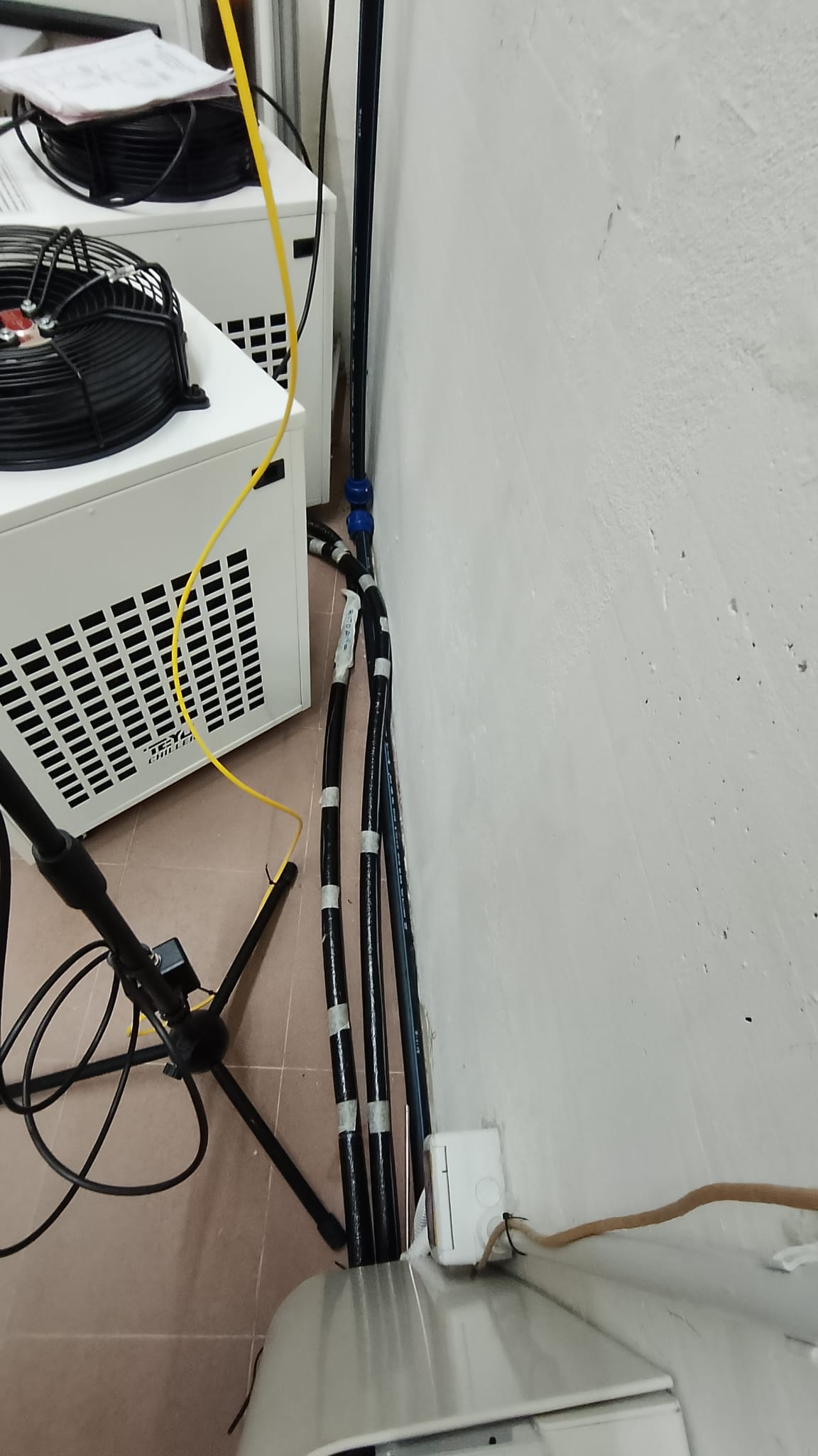
1. Primary stage –. The tank temperature is maintained by one of two chillers, operating in a redundant configuration: one unit designated as the primary chiller (working) and a second unit
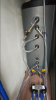
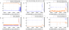
as a (non operating until needed) backup, to ensure continuous operation. In case of failure, the operator on shift will only have to switch the piping from one chiller to the other (pic 2: AuxCooling Chiller)
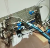
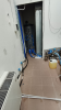
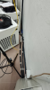
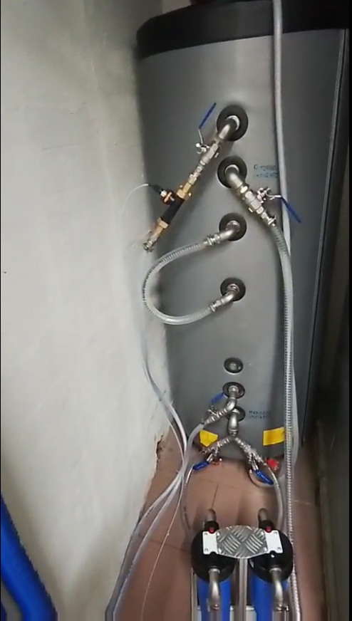
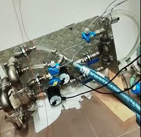
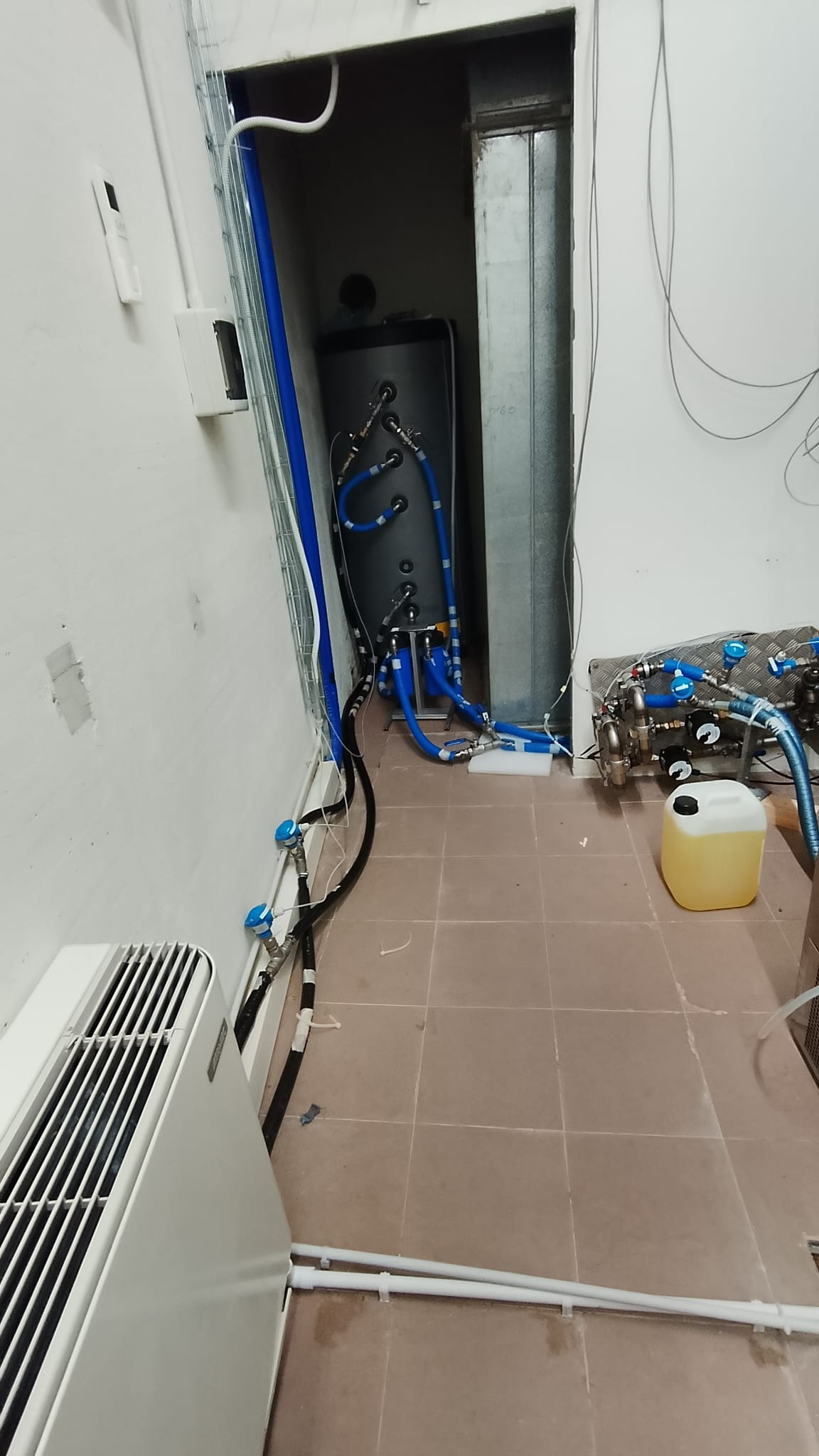
2. Secondary stage – From the tank (pic 3 - AuxCooling Tank), water is distributed through two separate piping and valve systems, one per laser (pic 4 (temporary) - Distribution and post-heating system assembly phase). Each system includes four pipe collar heaters, enabling post-heating control of the oscilations in temperature, to keep them within the 0.1 limit (more details in future entries that will be posted as comments of this one).


New sensors were installed and new channels were created, soon to be implemented on DMS. Together with the old ones, the system can be monitored using (see schematics)

  1. INF_TCS_AuxCooling_Pri_OUT_TE (chiller --> tank)
  2. INF_TCS_AuxCooling_Pri_IN_TE (tank --> chiller)
  3. INF_TCS_AuxCooling_Pri_FLOW (chiller --> tank) 
  4. INF_TCS_AuxCooling_Tank_OUT_TE (tank --> circulators)
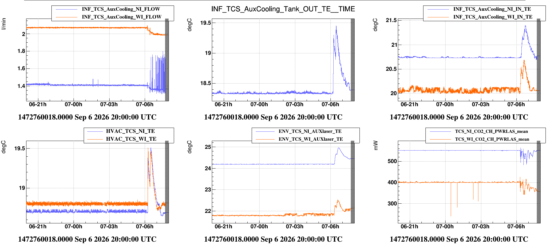
  5. INF_TCS_AuxCooling_NI_IN_TE (NI utilities --> tank)
  6. INF_TCS_AuxCooling_WI_IN_TE (WI utilities --> tank)
  7. INF_TCS_AuxCooling_NI_FLOW (NI utilities --> tank)
  8. INF_TCS_AuxCooling_WI_FLOW (WI utilities --> tank)
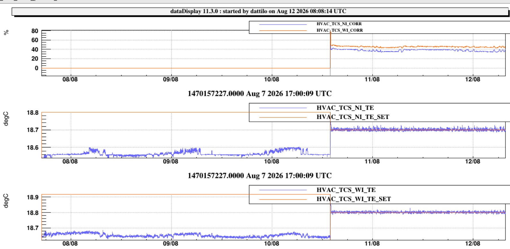
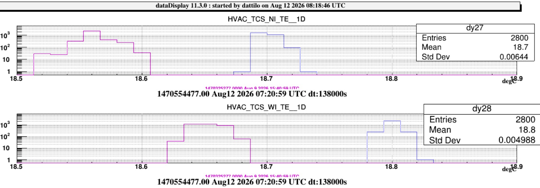
  9. HVAC_TCS_NI_TE (placed after the resistors, used for the post-heating control loop)
  10. HVAC_TCS_NI_TE_SET (post-heating control loop)
  11. HVAC_TCS_NI_ALARM (post-heating control loop)
  12. HVAC_TCS_NI_CORR (post-heating control loop)
  13. HVAC_TCS_WI_TE (placed after the resistors, used for the post-heating control loop)
  14. HVAC_TCS_WI_TE_SET (post-heating control loop)
  15. HVAC_TCS_WI_ALARM (post-heating control loop)
  16. HVAC_TCS_WI_CORR (post-heating control loop)
  17. INF_TCS_AuxCooling_NI_IN (temperature of NI laser, already in use)
  18. INF_TCS_AuxCooling_WI_IN (temperature of WI laser, already in use)
  19. TCS_NI_CO2_CH_PWRLAS (NI laser power, already in use)
  20. TCS_WI_CO2_CH_PWRLAS (WI laser power, already in use)
Images attached to this report
Comments to this report:
zaza, menzione, spinicelli - 17:46 Thursday 06 August 2026 (69528) Print this report

The new system is now working steadily, at around 1.8 (NI) - 2 (WI) liters per minute.


Before shutting the old system off, issues and anomalies with the flows (both NI and WI) were observed.

This phenomenon can be a consequence of the following issues:
Clogging in the piping
Clogging in the fittings
Clogging in the utilities
Old or damaged flowmeters
Presence of air
Insufficient circulators
Losses in the circuit

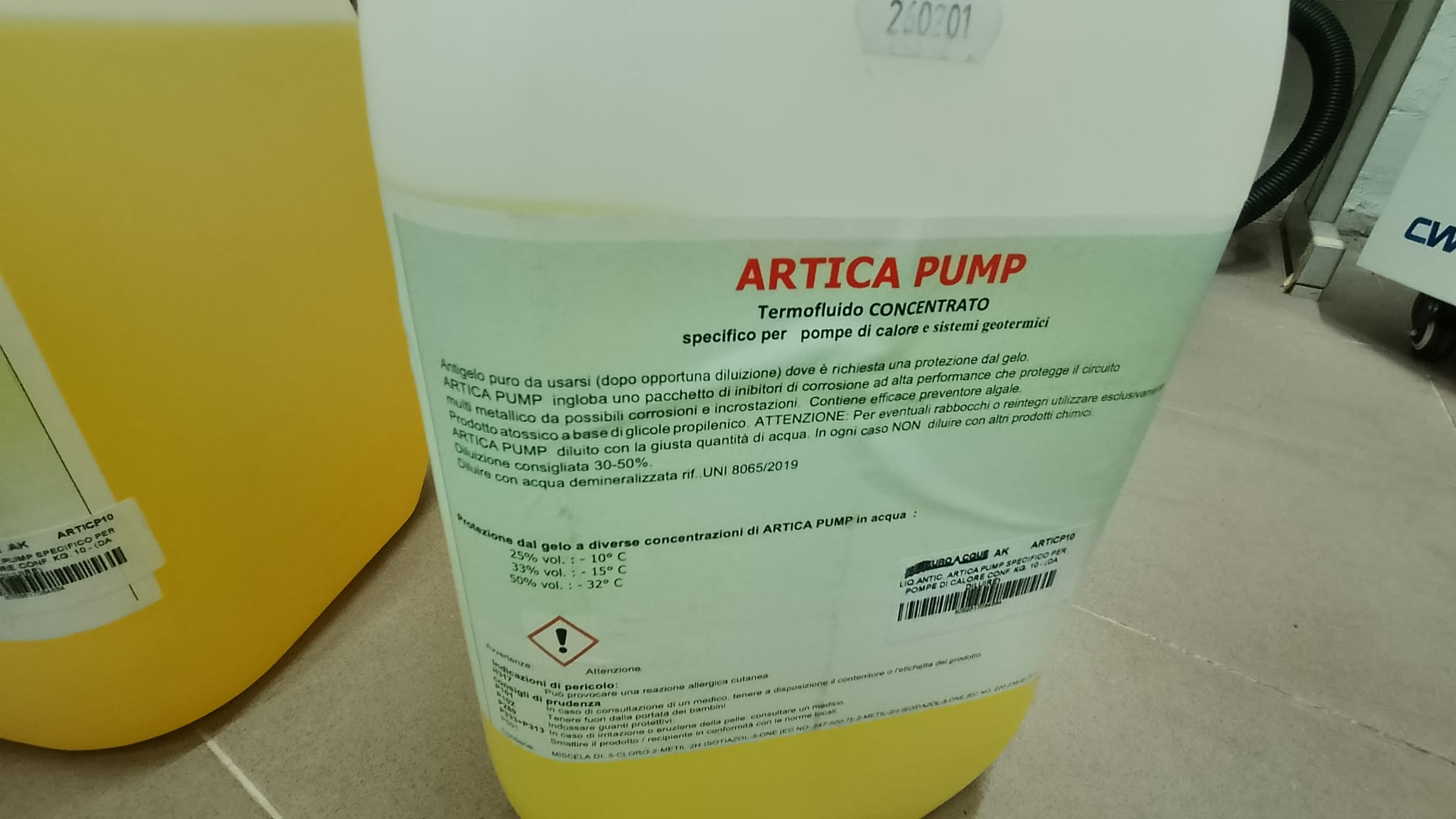
The new cooling system was designed specifically to comply to the correct water treatment and choice of materials to avoid future corrosion, deposition, erosion, pitting or biologic contamination and the flowmeters already in place were replaced. Air was completely removed and the circulator's power was doubled (from a single one for two branches to two separate ones).

Still, the measured flow of the new system was the same or lower than the old one, even when switching back to the old flowmeters, that show the same measurements as the new ones.

First thing that needs to be taken into account is that during the installation the system remained filled with still water for more than a month, so if any debris were present they might have deposited.
This is why Nicola, Piernicola and I carried out a thorough cleaning of every piece of piping and every fitting, laser area included, with air, mechanical friction, alcaline soap and both alcohol and ultrapure water ultrasound bath.
We inverted the laser's inlet and outlet from the circulators onwards and closed the system on itself at every level. The results are the following:
 

The flow up to the split among the utilities, under the bench, is 10 l/min.
After the splitting into 8 utilities, it decreases to 2 l/min (acceptable according to the laser manufacturer)
We tested every utility and found some beam dump to be completely clogged so that not even air could go through. The laser, nevertheless, after being cleaned with dust-free cloths and distilled watere, showed no working issues


While dismantling and cleaning the old system, debris were collected and biological contamination was observed. They will be sent to an external laboratory to be analized.
Water pH was between 6 and 6.5.

TDS document addressing pollution in cooling systems coming soon

Search Help
×

Warning

Error

The present report has been modified outside this window. Please check for its integrity in the main page.

Refreshing this page will move this report into drafts.

×