Before measuring the locking bandwidth, the OLTF of the IMC was measured, and a 14° phase margin was measured.
We measure the locking bandwidth, which is the linearity zone between the SL cavlty length and the error signal. Initially, it was measured at 0.9 MHz
After turning the LB_M2 mirror horizonally, we managed to increase the bandwidth up to 1.3 MHz. After that, we measured the IMC OLTF again, and found a 19° phase marging.
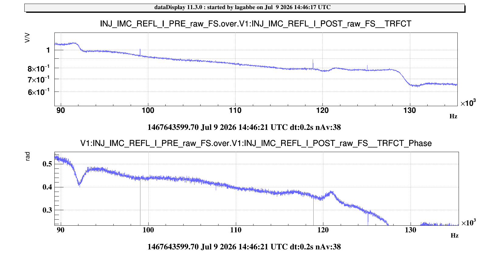
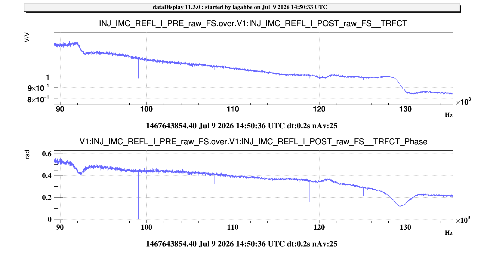
After that, we tried to realign LB_M2 vertically, we managed to reach a 1.0 MHz bandwidth. The UGF of the IMC OLTF was 92kHz with a 23° phase margin. In order to increase the UGF, we diminished to IMC loop attenuator value from 11dB to 9dB, which increase the main gain of the loop. The new UGF is 120kHz with a 20° phase margin. The two plots shows the OLTF of the IMC with the attenuator at 11dB and at 9 dB.
Other subject: In order to stabilize the TY degree of freedom EIB, we moved the the water tubes of IPC1. It improves the TY value and releases a bit the actuator 0.