This morning we worked on reducing the power on B1s in order to lock the ITF in LN2 without requiring manual SR misalignment.
When the WI CO₂ laser was replaced in 2024 (64847), a similar issue was observed and mitigated by moving the WI DAS in the horizontal direction ( 64851-64865).
Thus, today we acted in the same way.
We applied 5 steps:
STEP 1: with the ITF in LN2 (locked at 8.48 UTC), at 8:57 UTC we moved WI DAS by 1.5 cm (5556 + 2778 steps) in the forward direction. The ITF unlocked immediately after the DAS movement due to an increase of B1s power above the shutter threshold.
CARM NULL 1F reached again at 9:11 UTC.
STEP 2: We agreed to come back 1 cm (5556 steps backward) at 09:18 UTC.
After this step, the situation improved:
-
12 MHz: 0.038 mW (with respect to tonight’s CARM NULL value of 0.036 mW)
-
112 MHz: 0.0255 mW (with respect to tonight’s CARM NULL value of 0.024 mW)
-
B1p: 0.020 mW (with respect to tonight’s CARM NULL value of 0.018 mW)
We then proceeded with the lock acquisition by misaligning the SR by 0.5 µrad. However, the ITF unlocked at 09:57 UTC during ACQUIRE_LOW_NOISE_2, but not due to B1s saturation (cause unclear).
The subsequent lock acquisition did not show any issues, and the ITF locked again at 10:09 UTC in CARM NULL 1F. Then, we proceeded to LN2 without misaligning the SR; the procedure was successful and the ITF locked in LN2 at 10:29 UTC.
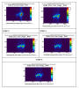
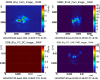
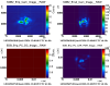
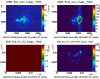
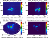
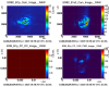
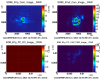
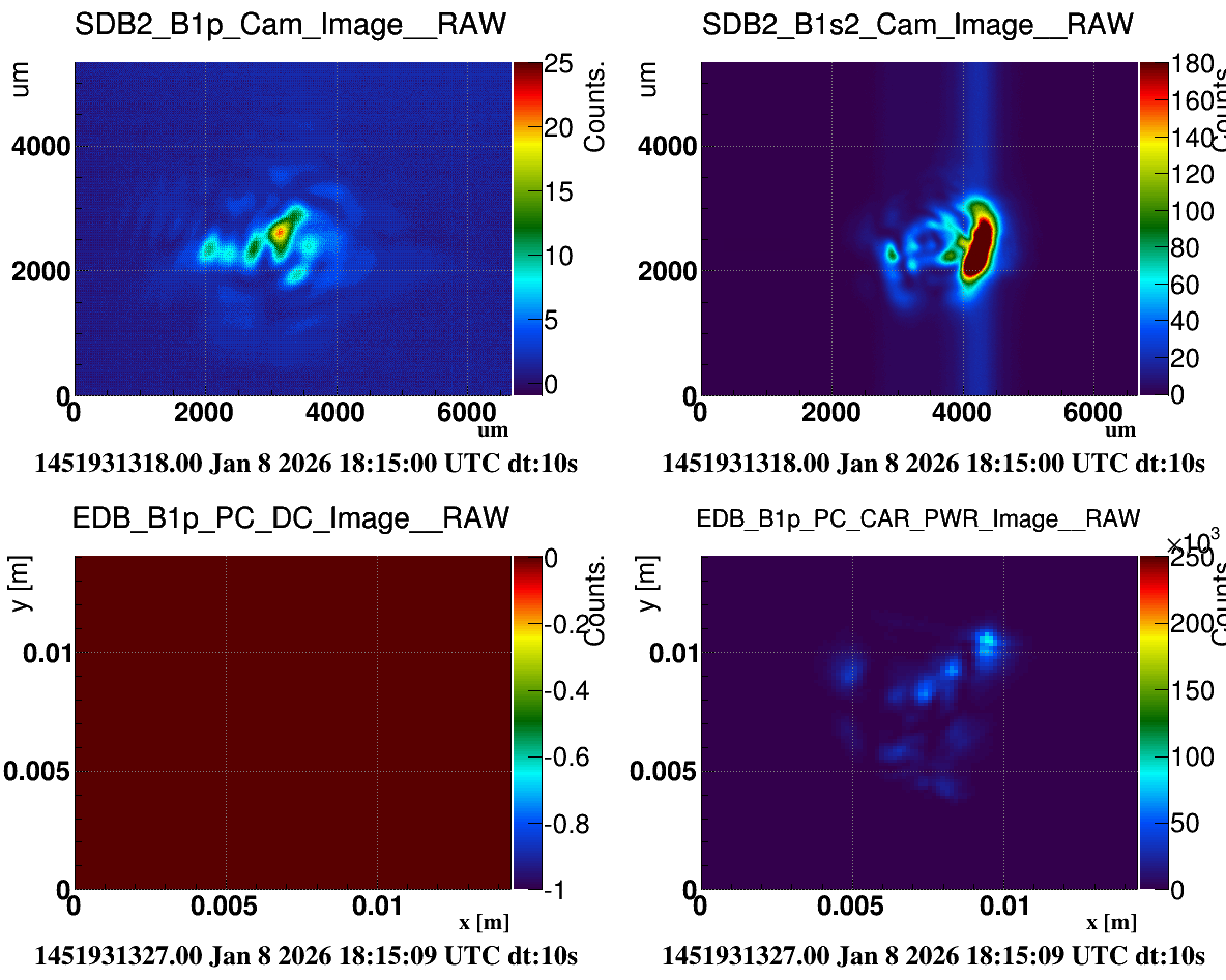
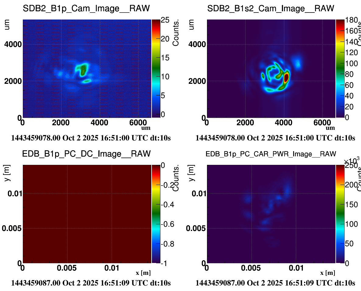
The bump in the right part of the camera of B1s is still present but it was less brighter (see figure 1- STEP 2). Thus, we performed a new step in the same direction .
STEP 3: 11:01 UTC, we completed a movement 0.25 cm forward (1389 steps).
STEP 4: 11:31 UTC, we completed another movement 0.25 cm forward (1389 steps)
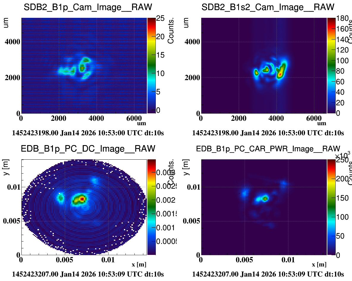
Looking at the B1s camera, we observed that the spot moved to the left side of the camera (see figure 1- STEP 4). Therefore, we reversed the step by half to improve the left-right asimmetry .
STEP 5: 12:53 UTC, we completed another movement 0.125 cm backward (694 steps).
After these steps, the situation appeared to be worse with respect to STEP 4. Therefore, the last step (STEP 5) was completely reverted at 13:48 UTC.
Thus, overall, we moved the WI DAS by 1 cm with respect to the nominal position, in the right direction on the cardboard (and on the CP).
The ITF was then manually unlocked at 14:27 UTC to check the lock acquisition procedure.
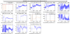
The main ITF signals during the shift are shown in fig. 2.
The ITF relocked in CARM NULL 1F at the first attempt at 15:43 UTC and in LN2 at 15.01 UTC.
