Yesterday during the maintainance, we had another attempts to meausre the V-H coupling with the filter cavity end mirrors.
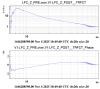
Since during our last measurement, we noticed the coupling between the longitudinal and TX, which might be caused by the unbalanced actuators on the mirror, we first checked if this coupling could be reduced by changing the actuation matrix. Currently the Z direction of the mirror use only the top and bottom actuators, so we tried to adjust coeffcients between them. The following three combinations were tested for the [Top, bottom], [+1.078,-0.922] (starting point), [+1,-1], [+0.9,-1.1], with a line injection at 7Hz to the logitudinal loop to check the coupling. In Fig 1, the spectrum of the AA TX (indication of the coupling) zoomed around 7Hz is shown for three matices as blue, purple and orange. It seems with the driving of [+1,-1], we reached a state with less coupling. Further test could be done to find the optimal actuation to further minimize the coupling.
Then we repeated the line injection in low frequency to the suspension Y, but after each injection, we realigned cavity with the AA loops. The time for each injections are listed below, the amplitude of the lines are 30.
4Hz 10:27:55 -- 10:31:00 UTC
5Hz 10:32:25 -- 10:35:20 UTC
7Hz 10:37:30 -- 10:39:50 UTC
Then we did a wide band noise injection between 7Hz and 50Hz,
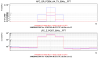
Filter cavity longitudinal lock open loop transfer function, noise amplitude of 3e-3: 10:46:25 -- 10:50:20 UTC
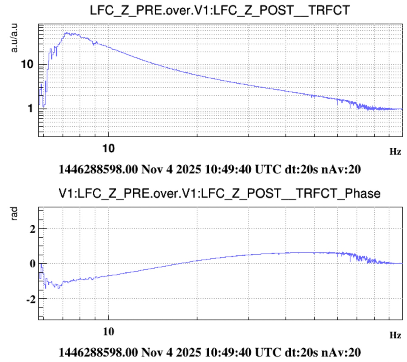
Noise injectio to FCEM suspension Y, noise amplitude 20: 11:05:15 -- 11:12:50 UTC
The analysis of the data will follow.