Reports 1-1 of 1 Clear search Modify search
AdV-COM (1/√f noise)
mwas - 22:05 Thursday 02 October 2025 (67850) Print this report
Mystery noise decreases in LN2 for worse OMC mode matching

Leaving SDB1 moved along Z axis by ~5 mm. In case of any problems
in the lock acquisition during the night the F0 X set point should be
moved back to its initial position, 2600 um X set.

This has improved the noise in LN2 by ~4Mpc, to be confirmed what it
does in LN3. In any case it doesnt' make it much worse as a few minutes after reaching LN3 the BNS range was 54Mpc.

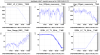
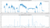
Figure 1 shows the translation of SDB1 along the beam axis that makes the BNS range better, but the optical gain worse. 
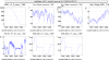
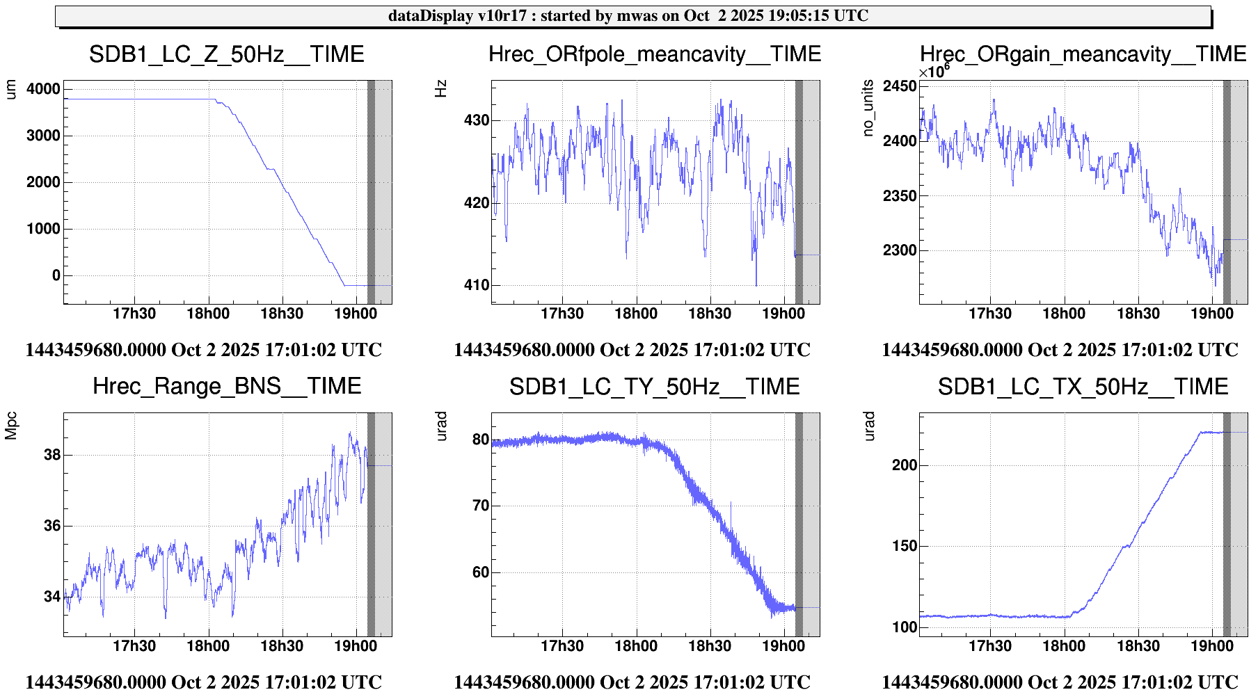
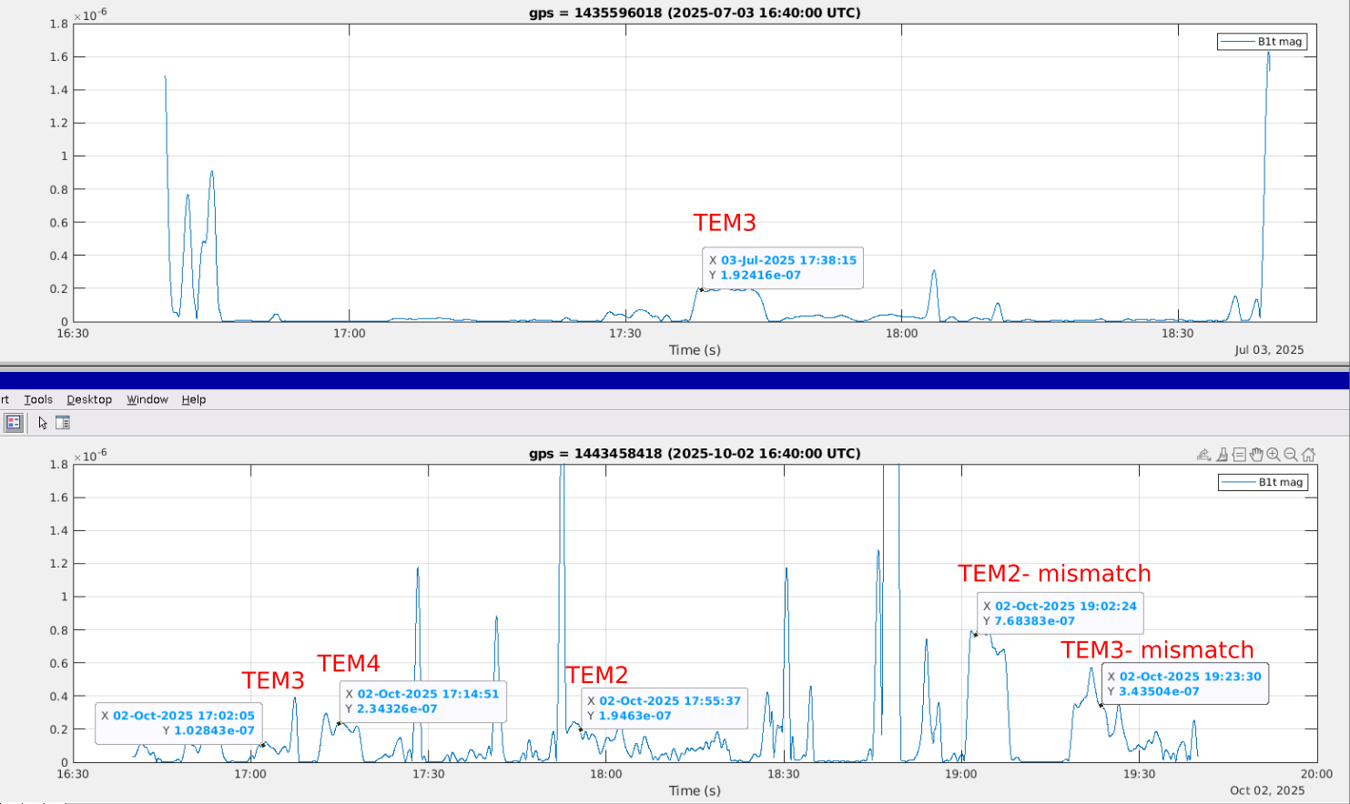
Figure 2 shows 

Some more detailed notes on the measurements done today with the EDB OMC that were the initial motivation of the shift. And some measurements done on Tuesday at the beginning of the IPATSiA shift.

The EDB B1t photodiode DC and Audio calibration needs to be updated, it is still using the parameters from before the photodiode replacement last week.

----
Sep 30

Locked on 56MHz sideband, I think it is the upper sideband, but I am
not quite sure. And did adjusted of 100-200 step on EDB_OMC1_TX/TY

17:32 UTC (3 min) calm data after realignment

Started scan with same parameters as last time. frequency 0.002Hz,
amplitude 0.5 degree, offset 23.27 degree. This corresponds to a one
degree step in the starting point. I guess with the air flux in
reduced mode the working temperature is higher than in high air flux
as used last week during the tuning of the photodiode during work on
SDB2 with people present in the room for several days. So beginning of this scan will be highly non linear. 

turned off EDB picomotors

------
Oct 2

The Bt1 photodiode Volt to Watt conversion factor have not been
updated after the PD swap. So the channels are no longer properly
calibrated. The DC channel is a factor 2 smaller than the Audio one. I
am not sure what is the absolute calibration either. In the analysis I
have multiplied the DC channel by 2 to match the Audio one, and
assumed the Audio one is correct, which gives a resonable level of
noise at high frequency that can be explained as shot noise.

Interferometer in LN2

15:43 UTC - lock on 56MHz USB, turn on pico-motors. Managed to almost
completely remove the beam jitter peaks at a few hundred Hz.

15:58 UTC (5min) 56MHz USB quiet data. The beam jitter peaks remained
low for the 5min of the measurement

turned off picomotor driver

when passing thurog 56MHz USB order 1 mode it was mostly vertical and
5 times lower in power than TEM00

16:10 UTC (5min) order 2 carrier - spoiled by saturation

noticed that B1t Audio saturates all the time on the order 2 and 3 modes

reduced DIFFp TX/TY lines to the LN3 amplitude (instead of LN2)

16:40 UTC (5min) order 3 carrier

reduced DIFFp TX line by another 25%

16:51 UTC (5min) order 2 carrier 

17:02 UTC (5min) order 3 carrier

17:13 UTC (5min) order 4 carrier

17:24 UTC (5min) order 5 carrier

17:35 UTC (5min) order 6 carrier

17:53 UTC (5min) order 2 carrier

18:01 Moving SDB1 suspension, F0 X starting point 2600 um

this misaligns the EDB OMC, relocking on 56MHz USB TEM00

turning EDB picomotors on realigning EDB OMC in vertical as the
translation of SDB1 along the beam axis progress.

The optical gain is decreasing (OMC mode matching getting worse), but
the BNS range is clearly improving by several Mpc. The SDB1 B5
quadrant has the beam near the edge of the linear range so going
further is not reasonable. Stopping with F0 X at -2200, so 4.8mm total
motion according to F0 position calibration.

19:03 UTC (5min) order 2 carrier

19:21 UTC (5min) order 3 carrier

19:27 going to LN3 with EDB OMC remaining locked on order 3 carrier
mode. However the EDB OMC will get misaligned as the bench turns to
keep the SDB1 OMC aligned.
 

Images attached to this report
Comments to this report:
mwas - 11:05 Friday 03 October 2025 (67854) Print this report

A plausible explanation for the BNS range in LN2 getting better when degrading the optical by changing the OMC mode matching is that the beam from the two arms at the beam splitter are not well matched. Either because the beam waist radius and position in the two arms is different, or because the lenses in the IM/CP are different causing the wavefronts from the two arms at the beam splitter to have different curvature. This would mean that part of the phase fluctuation corresponding to the DARM motion are not in the 00 mode after interference on the beam splitter, but are in the order 2 mode. The definition of 00 mode and order 2 are depending on the basis chosen for the decomposition, the sum of a 00 mode and an order 2 mode is just a Gaussian TEM00 mode with a different waist radius and position. 

Lets assume that the OMC and the north arm are perfectly mode matched, and use that basis for the decomposition. Then the west arm will produce a DARM signal that is in the TEM00 mode and in the order 2 mode, while the north arm produces the DARM signal only in the TEM00 mode. That order 2 mode signal can beat with a static order 2 field that is resonating in the recycling cavities, and happens to be in the DC read-out quadrature to sense the changes in phase of the order 2 mode coming from the west arm. This is a configuration that can be good from the noise perspective, because the OMC will reject the order 2 mode from the west arm, but bad from the point of view of optical gain, becasue the OMC rejects the part of the DARM signal which is in the order 2 mode.

Lets then adjust the OMC mode matching to be halfway in between the north arm and the west arm, while keeping the same TEM decomposition basis for the reasoning. If one looks in a two dimensional space with the 00 mode on the horizontal axis and the order 2 mode in the vertical axis, the north arm will have a field in the horizontal direction, and the west arm has a field with an angle alpha. In this for an OMC perfectly mode matched to the north arm the optical gain would be proportional to 1+cos(alpha) while the maximum optical gain is achieved for an OMC halfway in between the two arms and that maximum corresponds to a gain of 2*cos(alpha/2). To have a 5% change in optical gain  due to such a change the angle alpha would need to be at least 0.65 rad, which would mean at least 36% of the signal is in the order 2 mode. This is a large number, I am not sure that it is plausible. However, one should remember that for the TEM00 the local oscillator has 6.3mW of power, while for the order 2 mode it is a few tens of mW, so the order 2 mode DARM signal is beating against a large field, which increases the DC readout DARM signal for the order 2 mode by a factor few.

Figure 1 shows the data trends during the SDB1 translation, showing the 5% change in measured optical gain. The EDB OMC was also locked on the order 2 mode for some part of that period, the power decreases from 1mW to 0.7mW,  in between there is realignment of the EDB OMC. However, for all of these cases the EDB OMC alignment may not be good even at the 20% level, so I am not sure that is significant.

Figure 2 and 3 shows the order 2 mode carrier frequency noise to B1 on the ~10.7kHz order 2 mode that resonates in the arms, it changes in height during the SDB1 displacement, mostly the peak at 10.87kHz increases in amplitude by a factor 3. The peak at 10.7kHz also increases. 

A way to try to investigate more this hypothesis is to check if we have past data with DAS power changes while the interferometer was locked in LN2.

In terms of simulation, Optocad shows that a 5mm displacement of the meniscus lens should correspond to the waist of the beam at the input of the OMC moving by 150mm, which is half of the Rayleigh range of the beam in front of the OMC. It also corresponds to an overlap of 94% between the beam and the OMC mode, assuming that before the displacement of 5mm the OMC is perfectly mode matched. To explain a 5% decrease in optical gain, the mode match in terms of power needs to get worse by 10%. For example if the beam waist to start with was not well tuned and 100mm from the OMC waist, then increasing it to 250mm would decrease the overlap with the OMC mode from 97% to 85%. So the loss in optical gain of 5% when mistuning the OMC mode matching is well explained by the expect mode match loss due to a 5mm bench displacement.

Images attached to this comment
mwas - 20:30 Thursday 09 October 2025 (67899) Print this report

A few weeks ago Fiodor had noticed that the DARM line has a very high coupling for the order 3 mode in the July measurements with the EDB OMC https://logbook.virgo-gw.eu/virgo/?r=67798

Unfortunately this has not been reproduced with the measurements on Oct 2.

Figure 1 shows the measurements from July in the top pane and the ones from October in the bottom one. It is B1t Audio demodulated at the frequency of the 74.4Hz DARM line. The times when the EDB OMC was locked on some of the higher order modes is written in red on the figure, for both panes the vertical scale is the same, however for the bottom figure there might be a factor ~2 error in the calibration of the data due to change in B1t photodiode in September. 

In July the order 3 mode was clearly with the highest DARM line out of all of the modes analyzed. In October the order 4 and 2 modes had a factor 2 more of DARM line.

Figure 2 shows the DC power and the DARM demodulated signal on EDB B1t during the Oct measurements. Unlike in most previous cases the order 3 mode did not have the highest power on Oct 2, instead the order 2 and 4 modes had a higher power, at least until the SDB1 bench was moved to in principle make the OMC mode matching worse.


/users/mwas/ISC/EDB_B1t_demod_20251002/EDB_B1t_demod.m

Images attached to this comment
Search Help
×

Warning

Error

The present report has been modified outside this window. Please check for its integrity in the main page.

Refreshing this page will move this report into drafts.

×