Reports 1-1 of 1 Clear search Modify search
AdV-SGD (FDS commissioning)
Zendri, De Rossi, Laudenzi, Lunghini - 10:02 Thursday 15 May 2025 (66789) Print this report
Hardware installation for the in fiber phase noise cancellation loop

This is a report on the hardware installations, performed on May 13th,  for  the  phase noise cancellation loop  of the fiber   between Inj and EQB1. The installations involved several laboratories

Atrium:

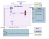
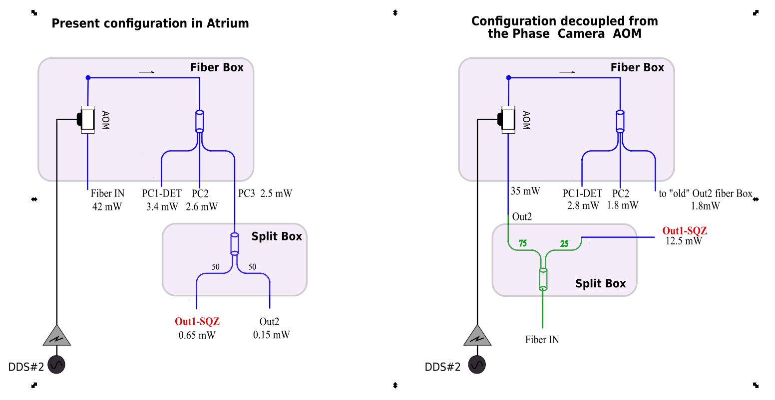
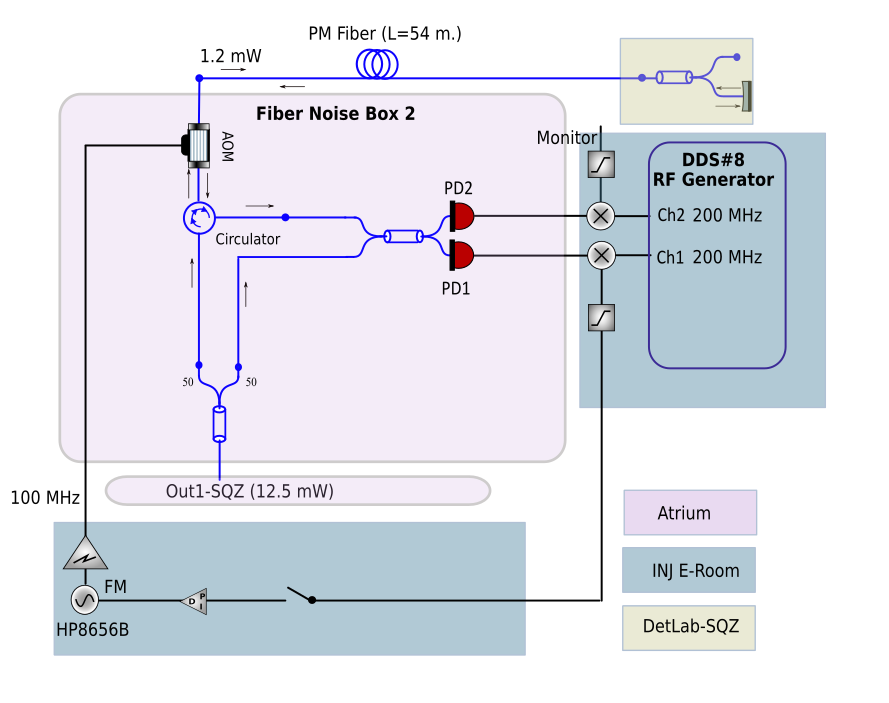
The fiber circuit of the phase camera and the squeezing in atrium has been modified  (figures 1,2)  in order to decouple the phase camera outputs from the one used to power the box “phase noise box” (fig3) containing the setup for the fiber phase noise cancellation loop . In this way, for the phase noise cancellation loop, we act on a dedicated AOM (operating at 100 MHz) independent from that of the phase camera.

Injection E-Lab:

The electronics for the phase noise cancellation have been installed in the Injection E-room. The installation includes a HP8656 RF generator equipped with a custom RF amplifier that serves to power the AOM at 100 MHz and a new 4-channel DDS generator that provide our low phase noise frequency reference (fig4)

DetLab (EQB1):

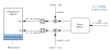
The optical fiber coming from the atrium to EQB1 has been split in two. One output goes to the main PLL of the squeezer as in the old set-up and the other branch to the fiber reflector (see fig 1 scheme).

Finally, 3 low attenuation RF cables (L=15 meters) were laid between the atrium and the E-room.

There was no time to test the loop operation, which will be done as soon as possible in agreement with the ITF planning. The feedback system is therefore left off.

Images attached to this report
Non-image files attached to this report
Comments to this report:
Zendri, Toffano, De Rossi - 9:22 Sunday 25 May 2025 (66848) Print this report

After the installation of the hardware for phase noise suppression the activities continued in the first part of this week:

1) New setpoint for the squeezer MAIN-PLL

The AOM dedicated to the fiber signal going to the squeezer operates at 100 MHz unlike the previous setup where the phase camera AOM was used ( 80 MHz) . We have therefore reset the squeezer main PLL with a frequency offset of 100 MHz. This is done by changing the PLL-LO frequency from 80 MHz to 100 MHz (see figure 1). To close the PLL loop we had to change the initial set point of the main laser peltir from 25780 to 25760. This last value was put in the squeezer automation configuration file (leaving the old one commented).

2)Characterization of the fiber  phase noise

The purpose of this activity is to monitor the phase noise acquired by the light propagating in the fiber  from Inj to DetLab (L=54m). First we set the parameters of the DDS#8 (see fig. 3 of #66789) in the following way

CH2-FIX frequency=99.99998566 MHz, amplitude (measured) 4.9 dBm

CH3-FIX frequency=199.99997132 MHz, amplitude (measured) 4.3 dBm

CH4-FIX frequency=199.99997132 MHz, amplitude (measured) 4.5 dBm

A 10 dB RF attenuator was inserted at the output of CH2 and the resulting signal was used as input to a customized amplifier (fig. 4 of #66789). Then the amplifier output (about 29 dBm) is used to drive the  AOM in the fiber box at 100 MHz.

After these operations we measured the RF powers of the PD1,2 at 200 MHz after the double pass in the AOM (fig. 4 of #66789) photodiodes which result

RF power -PD1: -4 dBm

RF power -PD2: -7 dBm

The reasn of this amplitude difference is not clear and needs to be investigated.

To estimate the in-phase noise acquired by the fiber we use the scheme in figure 2  but this requires re-starting some processes and will be done when possible.


Images attached to this comment
Non-image files attached to this comment
Search Help
×

Warning

Error

The present report has been modified outside this window. Please check for its integrity in the main page.

Refreshing this page will move this report into drafts.

×