Summary: IR cavity scan of North arm. Data anaysis ongoing.
Background: Poor mode matching causes several issues that limit the available power in the IFO, effectively increasing quantum and controls noise. The purpose of this investigation was to determine the mode matching and astigmatism in the north arm and compare against previous measurements.
Previously, the astigmatism in the north and west arms were estimated as follows:
| North Arm | West Arm | |
| Method 1 (cavity scan while misaligned) | 1.3 | 2.5 |
| Method 2 (Fit Airy peaks to cavity scan) | 2 | 2.5 |
It was determined that the Airy scan is better at fitting the overall astigmatism and the second method projects the astigmatism onto the axis of misaligment. This work is described fully in Cléments presentation.
We want to measure the astigmatism as it helps characterise the interferometer and determine which improvements can be made.
The Proposed Work
The West arm is currently being pumped down after WETM cleaning due to the point absorber. While we have north arm available, we decided the do the cavity scan. This is discussed in Issue 125 on the Commissioning Issue page.
Method
The procedure to scan both arms is to add an offset in the CARM loop while the arms are locked on green. The PRM and SRM should be misaligned. This procedure is described in the commissioning wiki (FSR Slow Scan)
We wrote a script for scanning just the north arm, while locked on green. The script is NARM_SET_scan_IR in the python module ITF_lock_library_HP. That module lives in /users/optics/ISC_scripts/.
We cannot feedback to CARM, instead we actuate on the test mass at LSC_ALS_NArm_SET, which adds an offset to the NITM mass. The green laser follows the cavity, actuating on the AOM to shift the green relative to the IR and keep it locked. This can be witnessed by inspecting the channel ALS_NEB_Corr_10KHz.
As far as I (AJ) am aware, the main laser is locked to the mode cleaner and there is no feedback to the main laser from the NARM. Therefore, we any IMC length noise will show up in our measurement. This needs to be confirmed.
We then estimated the voltage required at the OSEM to drive 1 FSR by trial and error. We know that when the cavity is locked we get 0.6mW in LSC_B7_DC, driving the error from -2V to 2V we saw at least two flashes of 0.6mW in one scan.
We then followed the following steps:
- Lock NARM on IR, wait for alignment to stablize
- Lock green aux to NARM
- Disable IR lock
- Enable green reallocation to test masses
- Load
ipythonin ISC_scripts,run ITF_lock_library_HP.py(to load function),run LSC_init.py(to enable CM) - At 17:01:36 [UTC+2], We ran a single IR scan (up and down) of NARM with 30 seconds ramp time, and 4V range
- At 17:05:03 [UTC+2], I ran 10 IR scans (up and down).
Results
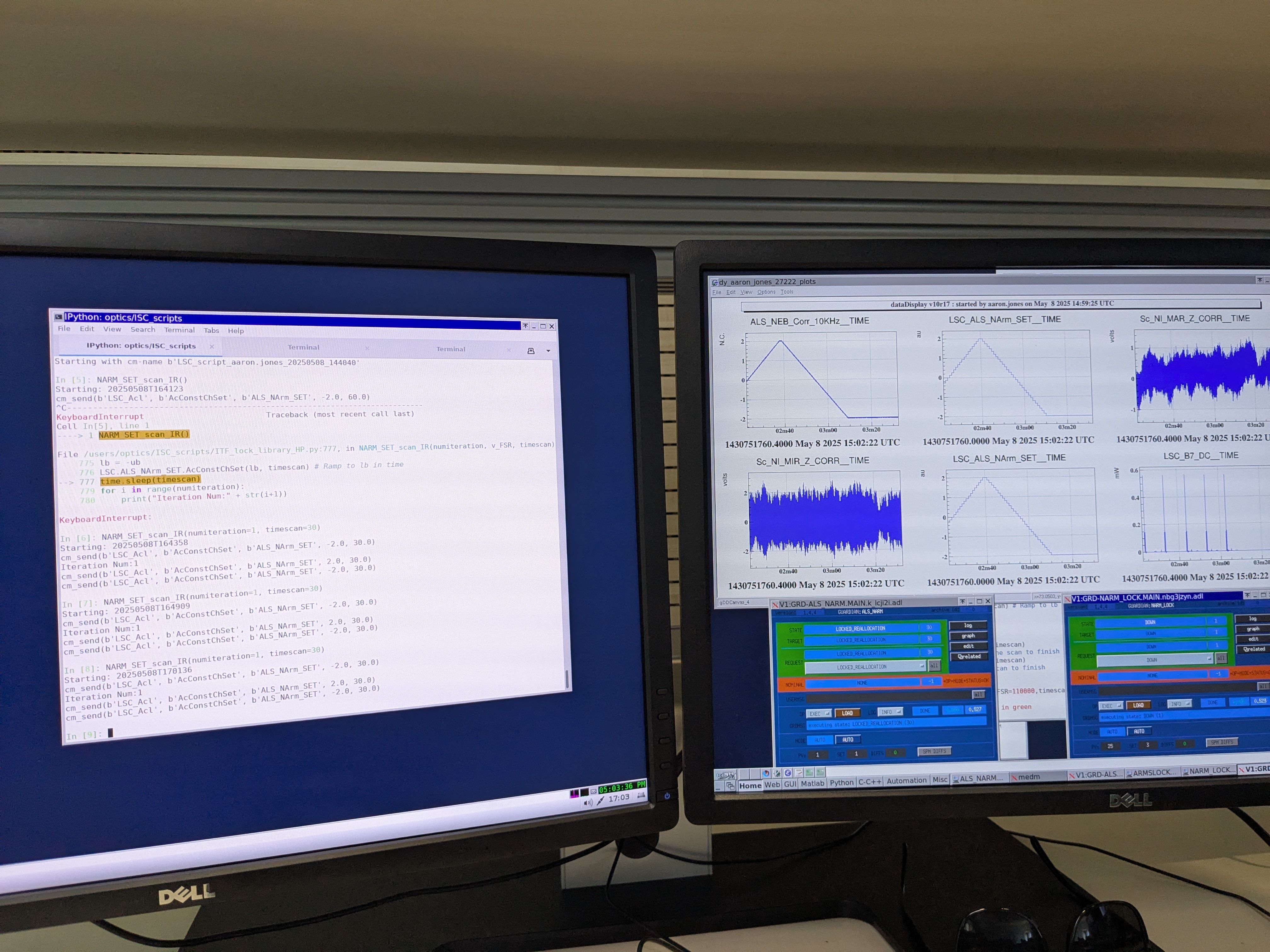
In the first attachment you can see:
- The IFO state (LOCKED_Reallocation & Down)
- The FSR down scan starts at 2m 40, as witnessed by LSC_ALS_NArm_SET and ALS_NEB_Corr_10KHz.
- Between 2m 40 and the end of the trace there are 3 flashes at 0.6 mW which we believe to be TEM00.
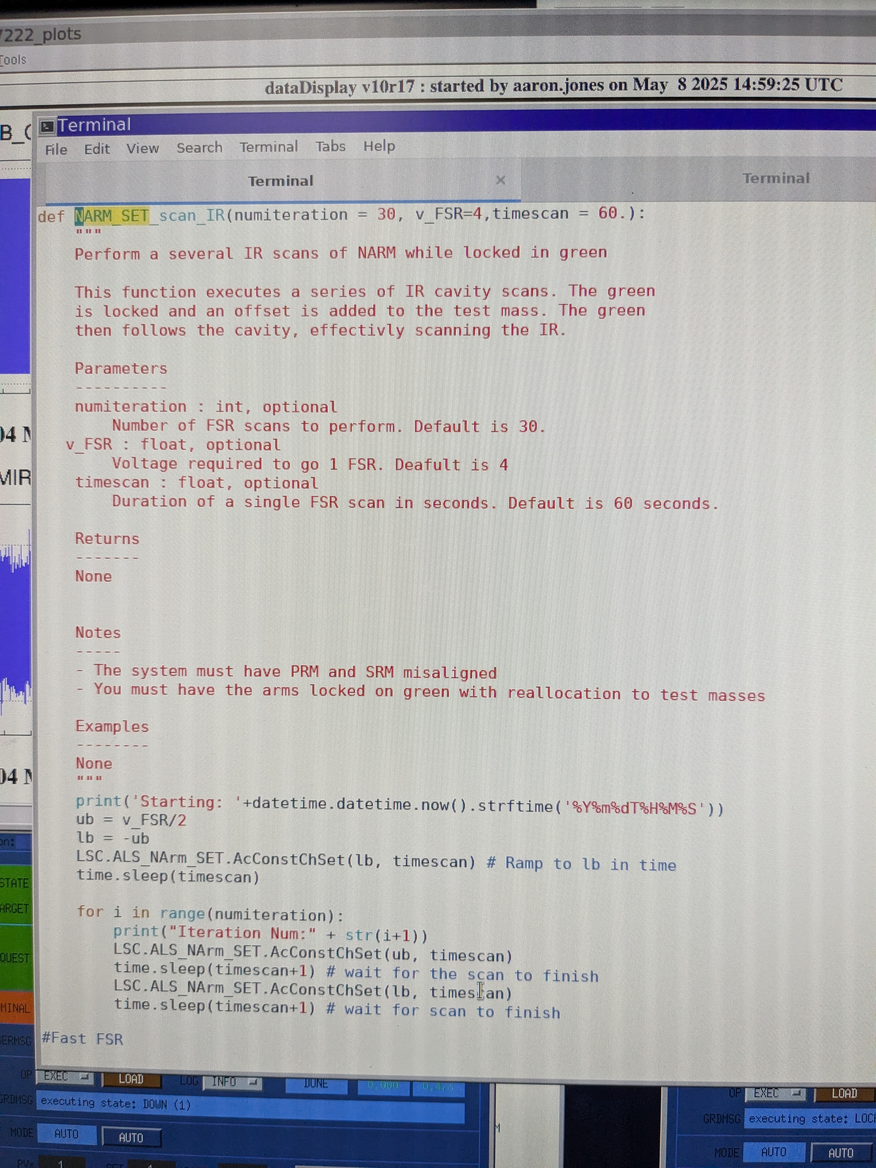
The second attachment shows a screenshot of the code.
Analysis and Interpreation
Analysis of the full stretch of data data will be carried out by Clément and posted to this elog. Data is available in the frame files.