Today I did an inspection of the hardware needed for testing the temperature control of the SQB1 FIs. Results
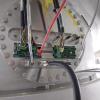
1)The cable for the peltier is connected to an SQB1 flange, black and thick cable in "SQB1Flange.jpg"
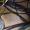
2) The cable enters the EE room where it splits. "Cable.jpg"
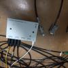
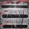
3)the split cables go partly to a Newport driver (grey box in the photo) used to move the HWPs and partly to 9 pin D-Sub connectors to be pluged in the peltier controlers "Newportbox.jpg". I found the Newport driver lying on the floor Now I have placed it in the "Armadio A2" rack
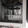
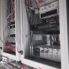
4) A possible place to install the peltier driver is the "Armadio A3" rack. This rack contains TCS devices but we have Ilaria's permission to use it. Under the controller there should be a place to install the Rodhe&Schwartz DC power supply to power the driver. "Rack2.jpg". The DC power supply was not installed because the person who took charge of it is on vacation. It will be installed upon his return.
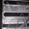
5) The DAQ boxes (4 ADC +2 DAC) to which connect the drivers could be those in the rack next to the driver (Armadio A2) "Tworacks.jpg" and "DAQBox1.jpg""The cables to go from the DAQ boxes to the drivers have be made. An alternative could be to use the DAQ boxes "DAQBoxe2.jpj" but they are installed 4 racks away from the driver.
I did not find any cable going from the EE det room to the Detlab for the EQB1 Faraday. A more systematic search will be done in the future. Otherwise a dedicated cable will have to be made
Finally with the support of Marco Vardaro I turned off the FCIM mirror controls.
