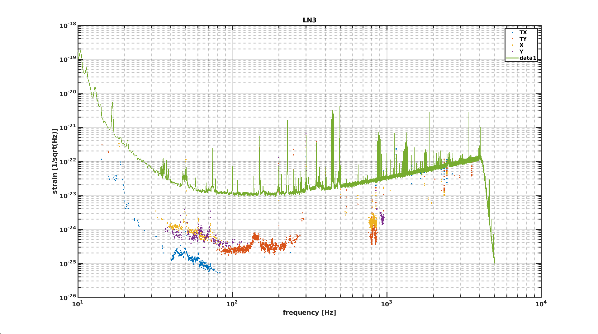
The goal of the shift is to measure the beam jitter coupling to the sensitivity in LN2 and LN3, because the measurement we have are too old. This will be useful to give an upper limit for phase II.
DSP card damping-adv BPCCD
page 4 wnoise 1
bpnoise bpnoise.flt 0.01 ( 2 zeros with Q=0 @0Hz, 1 pole with Q=0.5 @30Hz antd 1 pole with Q=0.5 @300Hz)
bp noise noise 1
amplitude set ont the dofs txcorr, tycorr, xcorr, ycorr
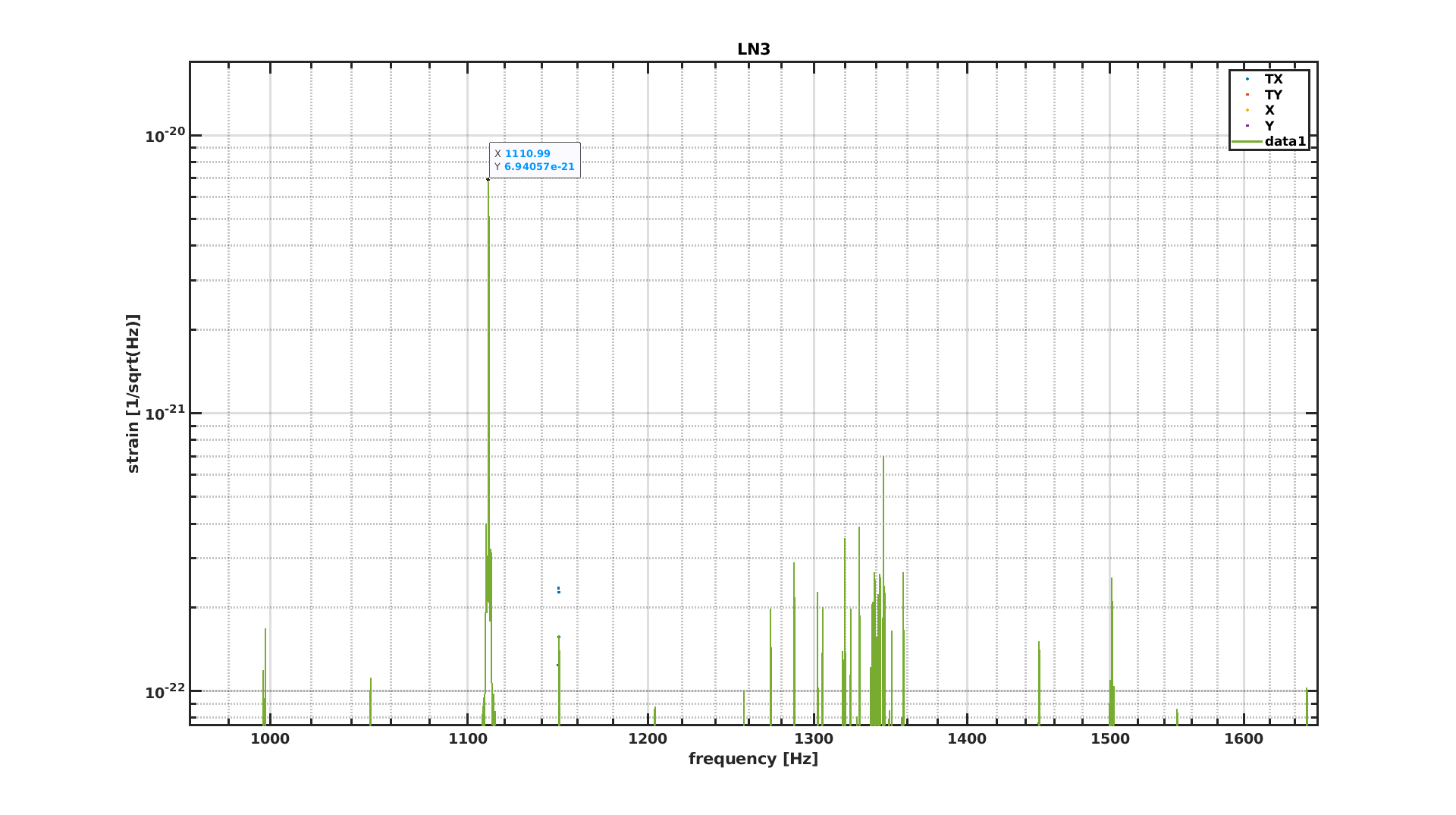
%%% LN3 %%%
| gps start | duration | amplitude | ITF status | |
| clean | 16:28:00 UTC | LN3 | ||
| TX | 1424104578 (16:36:00 UTC) | 2 min | 0.5 x 0.01 | LN3 |
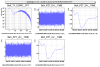
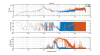
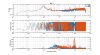
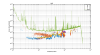
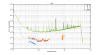
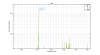
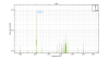
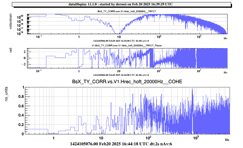
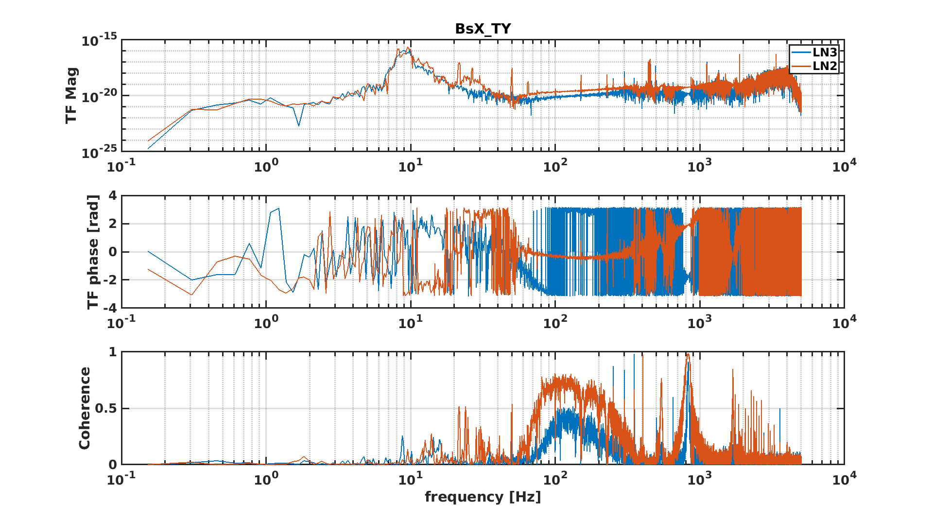
| TY | 1424195015 (16:43:20 UTC) | 4 min | 1.5 x 0.01 | LN3 (attached fig. as example) |
| TX | 1424105396 (16:49:40 UTC) | 4 min | 0.5 x 0.01 | LN3 |
| X | 1424105940 (16:58:40 UTC) | 4 min | 10 x 0.01 | LN3 |
| Y | 1424106374 (17:06:00 UTC) | 4 min | 10 x 0.01 | LN3 |
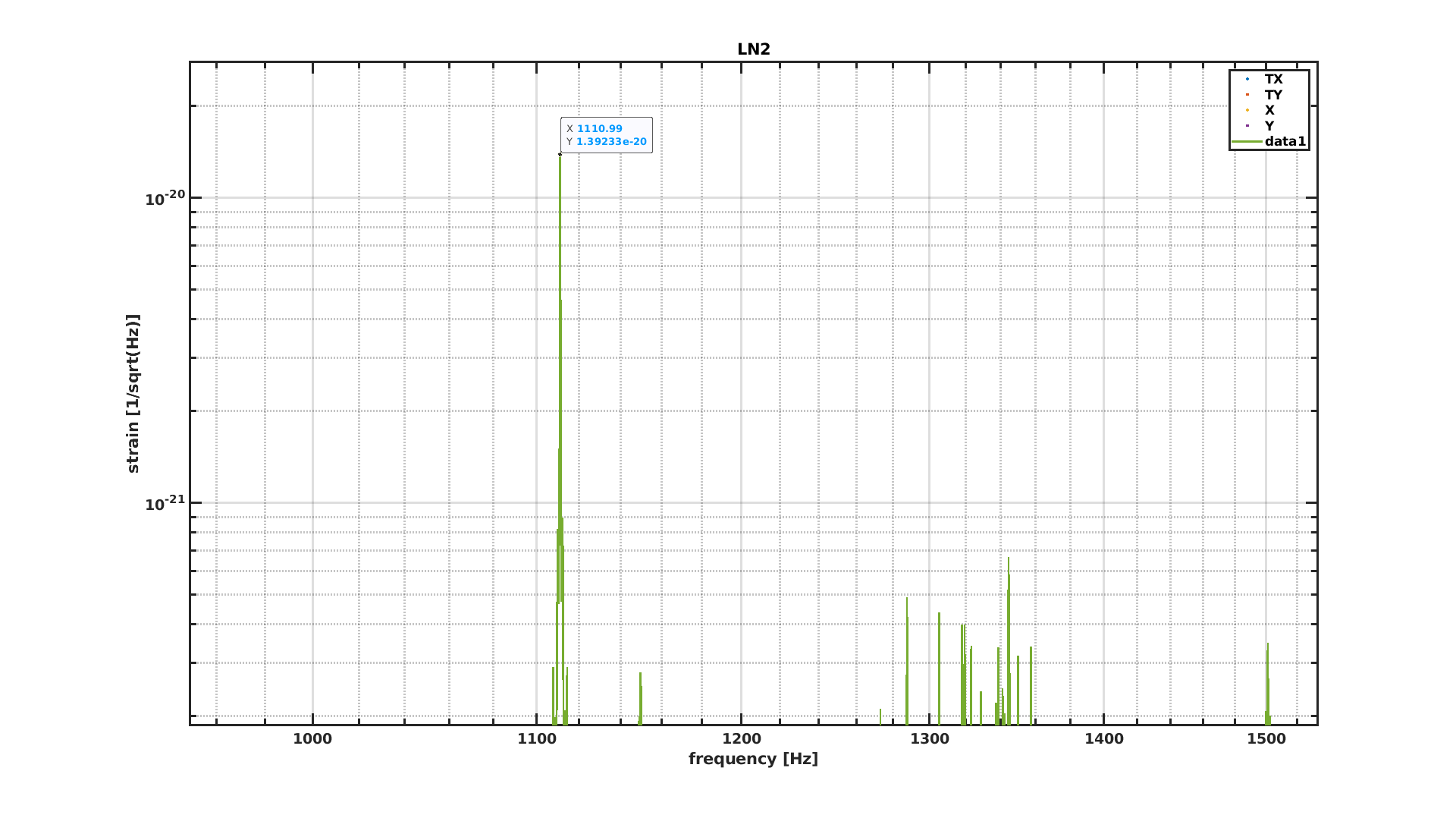
%%% LN2 %%%
| gps start | duration | amplitude | ITF status | |
| clean | 18:19:00 UTC | 2 min | LN2 | |
| TX | 1424110999 (18:23:00 UTC) | 4 min | 0.5 x 0.01 | LN2 |
| TY | 1424111568 (18:33:00 UTC) | 4 min | 1 x 0.01 | LN2 |
| X | 1424112122 (18:41:30 UTC) | 4 min | 10 x 0.01 | LN2 |
| Y | 1424112500 (18:48:30 UTC) | 4 min | 10 x 0.01 | LN2 |
| TY | 1424112839 (18:54:00 UTC) | 4 min | 1.5 x 0.01 | LN2 |
| clean | 19:00:00 UTC | 4 min | LN2 |


