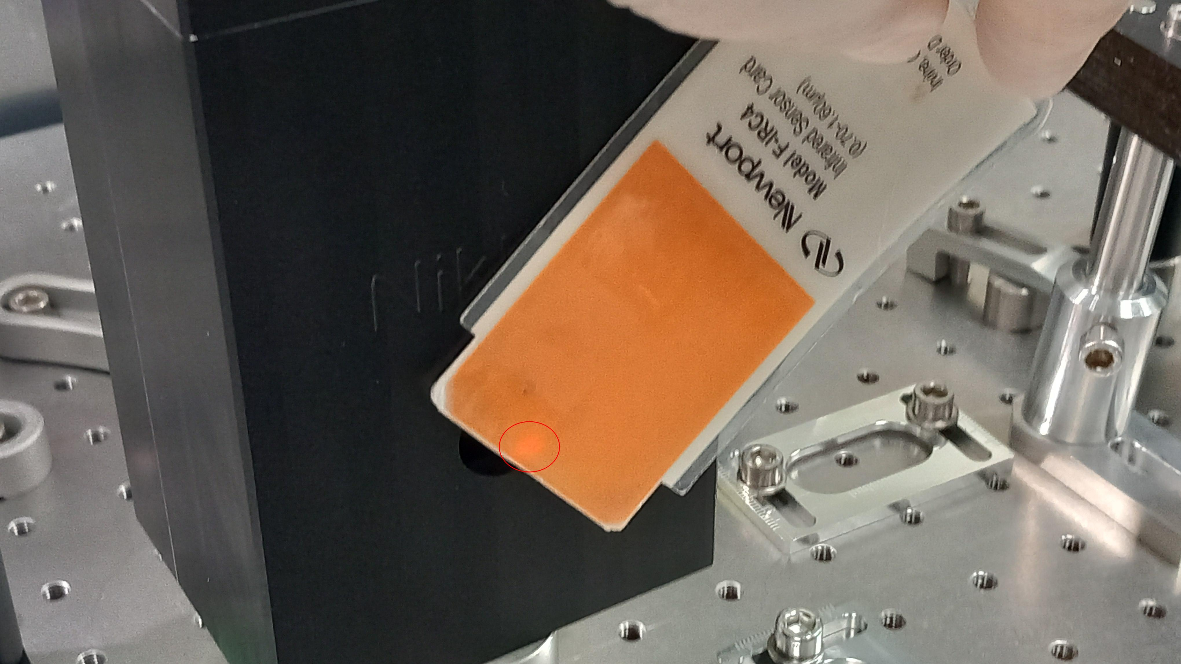
First we fixed the alignment of QD2 with the laser beam, which was misaligned as shown in figure 1. After this we realized that the sum signal of the 4 QD2 photodiodes was significantly larger than that of QD1 (6-7 Volt instead of about 2 Volt). Furthermore, contrary to the case of QD1, once the signal arriving at the photodiode was masked, “0” volts were not obtained in the sum channel but only a slight decrease of the order of 1 volt. This was an indication that there were also electronics problems.
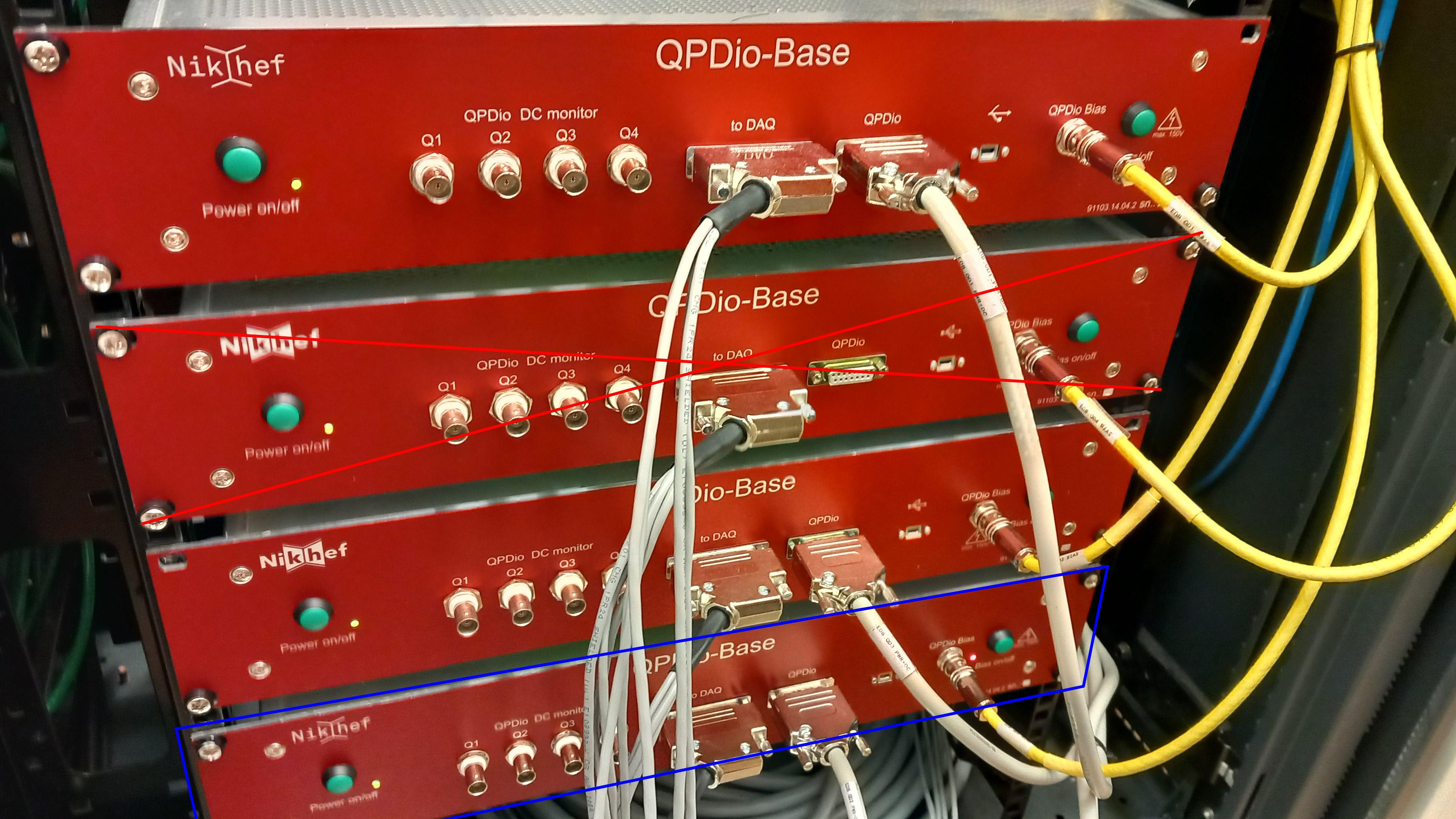
For this reason we decided to use the QD4 photodiode electronics (fourth QPDio-BASE from top in figure 2 ) which is currently not used, in place of the QD2 ones (second from top). Since this did not completely solve the problem we finally replaced the QD2 sensor with QD4. In this final configuration the photodiode sum signal appears to work correctly except for a negative sign and go to zero when the photodiode is masked. After investigation, it appears that the sign of the QD1 signal has been inverted in the config file "EDB_QD_AA.cfg", but not the sign of QD2 signal. So the four weights on lines 4 weights of line 1306,1307,1308,1309 has been changed from 1 to -1 finally getting the expected signal.
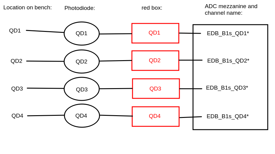
In conclusion, in the position of the second QPD used for alignment, the QD2 sensor has been replaced with the QD4 sensor with the relative QPDio-Base electronics. All the cables initially connected to the QD2 QPDio-Base box have been connected to the QD4 QPDio-Base box, so from the point of view of the DAQ channels nothing has changed, that is, the channels for alignment are still QD1 and QD2 (see figure NewConfig.png).
Finally the QD2 sensor has been removed and taken to the Padova/Trento office to be tested with the spare electronics.

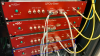
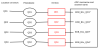
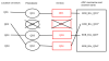
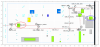
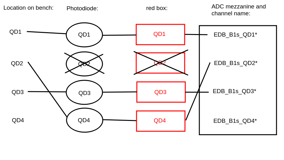
Figure 2025-01-21_EDB_scheme.png is the scheme of the EDB optical bench. The QD2 photodiode (circled in red) was replaced by the QD4 photodiode circled in blue.