Reports 1-1 of 1 Clear search Modify search
AdV-COM (1/√f noise)
mwas - 21:45 Thursday 07 November 2024 (65488) Print this report
Attempt at measuring sensitivity with SR aligned

Did not manage to make any clear measurement with SR aligned, but managed to do one SSFS noise injection with SR aligned (to be analyzed).

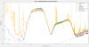
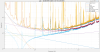
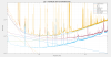
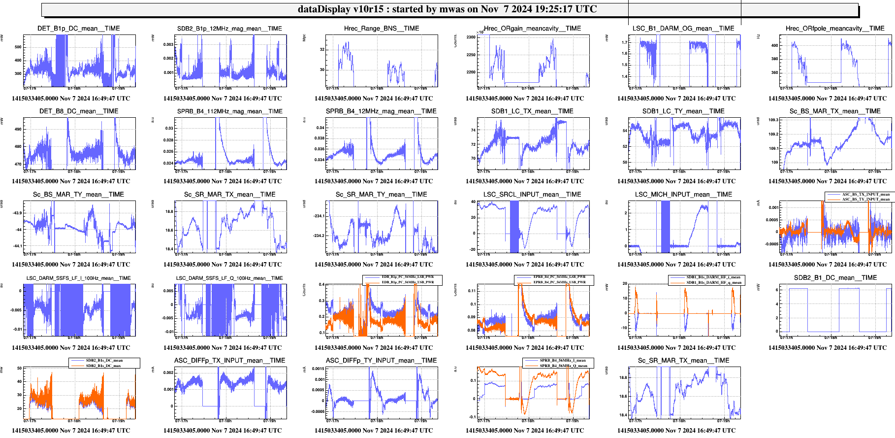
Figure 1 shows trend of data during the shift

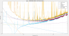
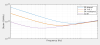
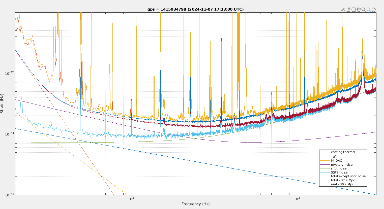
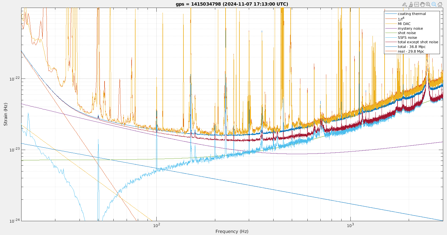
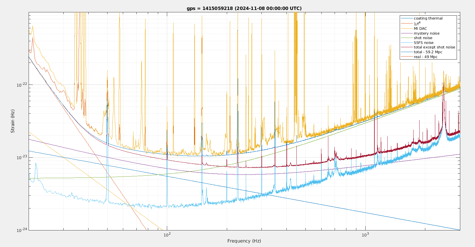
Figure 2 shows the fit of noise during the first SR aligned time with the LSC lines switched off and high frequency noise coupling. The 1/f^{2/3} required to fit the measurement is again factor 1.5 higher than when SR is misaligned.

Relock to LN2

Tried to do the steps of LN3 listed in /virgoDev/AEI_SQZ/changeDCP.py
and the adjusting BS TY to reduce the frequency noise coupling but that made the control less stable with more alignment
fluctuations, and eventually causing an unlock.

Relock to LN2.

Adjusting BS TX and TY to try to reduce frequency noise coupling, but again had issues with low frequency fluctuations causing an unlock.

Relock to LN2
Unlocked after 3 minutes while taking reference data

Relock to LN2

20:15 UTC - running the SSFS noise injection script

20:41 UTC - started taking reference time, but dark fringe started to fluctuate after a few minutes. Tried to go to LN3 to make it darker, but unlocked before SR had the time to misaligne.
 

/users/mwas/detchar/toySensitivity_20241107/toySensitivity.m

Images attached to this report
Comments to this report:
mwas - 14:15 Friday 08 November 2024 (65495) Print this report

Figure 1. Shows data during the SSFS noise injection, 10min of data includes several injection at different frequency bands together. The yellow line is the h(t) spectrum before noise subtraction performed by Hrec, red is after noise subtraction made by Hrec, and blue line is the total noise projection inicluding SSFS noise. It fits well

Figure 2. Shows the transfer function used to make the SSFS noise projection it is linear (not quadratic) sum of a frequency independent compentent and a 1/f component. The two components have opposite sign so below 200Hz the 1/f component cancels some of the frequency independent contribution. This is necessary to obtain a good fit with the measurement.

Figure 3 and 4 show the simplified noise budget on data in the 3 minutes preceeding the SSFS noise injection. The difference between the two curves is the method of computing the spectrum. Figure 3 uses the standard pwelch method while Figure 4 uses the median-mean spectrum computation method used in GW data analysis that reduces the impact of glitches, such as the 25 min glitches. The latter allows to see that the fit is reasonably good down to 50Hz. Note that the 1/f^{2/3} need to be scaled to be higher by a factor 1.8 than when SR is misaligned in order to match the total measured noise

Figure 5 shows the simplified noise budget for the previous lock, where 10 minutes of data is available, using the same SSFS noise transfer. In this case also a factor 1.8 of increase in 1/f^{2/3} noise compared to the SR aligned case is needed.

Figure 6 shows for reference a simplified noise budget from the night following these measurements. The SSFS noise coupling transfer function is fitted to measurement from Oct 28, and match frequency noise lines at 227Hz and the bump at 2.5kHz. In this case the 1/f component adds coherent with the frequency independent one. In any case for the SR misaligned case the frequency noise coupling is small, so the exact details of the noise projection do not matter as the contribution is negligible to the total noise.

/users/mwas/detchar/toySensitivity_20241107/toySensitivity.m

Images attached to this comment
mwas - 12:46 Saturday 09 November 2024 (65503) Print this report

When trying to simulate a DARM optical response transfer function in Optickle (plane wave simulation), an SR with 42% reflection and 12% losses reproduces the case of SR misaligned, while an SR with 60% reflection and 2% losses reproduces the SR aligned configuration.

The gain of a field added inside a cavity with losses is 1/(1 - sqrt(R)*sqrt(1-L)), which with the numbers above is equal to 4.29 for the SR aligned case and 2.55 for the SR misaligned case, which has a ratio of 1.7. So for an optical field resonating inside the SRC one would expect the field amplitude to decrease by a factor 1.7 when misaligning SR, this would be consistent with corresponding noise created by that field decreasing also by a factor 1.7, as the 1/f^{2/3} noise seems well explained by a noisy field beating against the DC read-out local oscillator.

Figure 1. Assuming that the noisy 1/f^{2/3} field is recycled by SR we speculate how it depends on the reflectivity of SR. The lines assume that the field is recycled by SR, and then attenuated by the SR transmission, and the DARM response transfer function was computed in optickle with 87kW in the arms for all the cases and 6.3mW of carrier TEM00 on the dark fringe. The SR aligned and misaligned configuration match the fit of 1/f^{2/3} verifying that there is no obvious mistake in the computation. SR with 70% transmission (that has same DCP as current SR misaligned configuration) would yield the same level of 1/f^{2/3} noise. And the no SR configuration matches the fit of "flat" noise in O3, with the big caveat that in O3 the noise level depedent on the DARM offset which is not the case of the 1/f^{2/3} noise. For the configuration without SR I assume no field amplification and that 100% of the field is transmitted by the SR lens.

Images attached to this comment
Search Help
×

Warning

×