This morning we continued the activities related to the detection tower intervention.
First we went to the CB platform in order to install an adaptor cable used for the driving of the new motorized agilis mount for the waveplate. In order to be able to cable this new device we sacrified the wires of the picomotor B5_M1_TX which was connected on the picomotor driver 8742 SN 10592, channel 4. We unplugged this cable, and connected it to the adaptor allowing to plug it on the Agilis driver AG_UC8, on the channel 3 axis 2. We updated the VPM configuration accordingly.
Then we entered the detection tower to check the new cabling. To this purpose we plugged a spare agilis rotation stage to the B5_M1_TX cable, and acted on the rotation stage from the SDB1_Rot process. The test was successful. After that we unplugged the tested spare rotation stage.
Then we performed a first measurement of the power delivered by the auxiliary laser placed on the bench. The power measured between the B1/B5 diaphragm was 237 mW, We also measured the power after the Faraday Isolator, by placing the power meter between the single hole diaphragm and SDB1_M3: the power was 63 mW.
Since the power was quite big, we installed a density in front of the laser collimator in order to reduce the laser power. After the installation of the density, we found a power of 18.7 mW before the B1/B5 diaphragm.
We then completed the alignment of the auxiliary laser setup, ensuring that the beam would reach the OMC and be reflected by it.
After the mirror alignment we took another laser power measurement at the same places:
* Before the B1/B5 diaphragm: 18.3 mW
* Between the single hole diaphragm and the SDB1_M3 mirror : 4.9 mW.
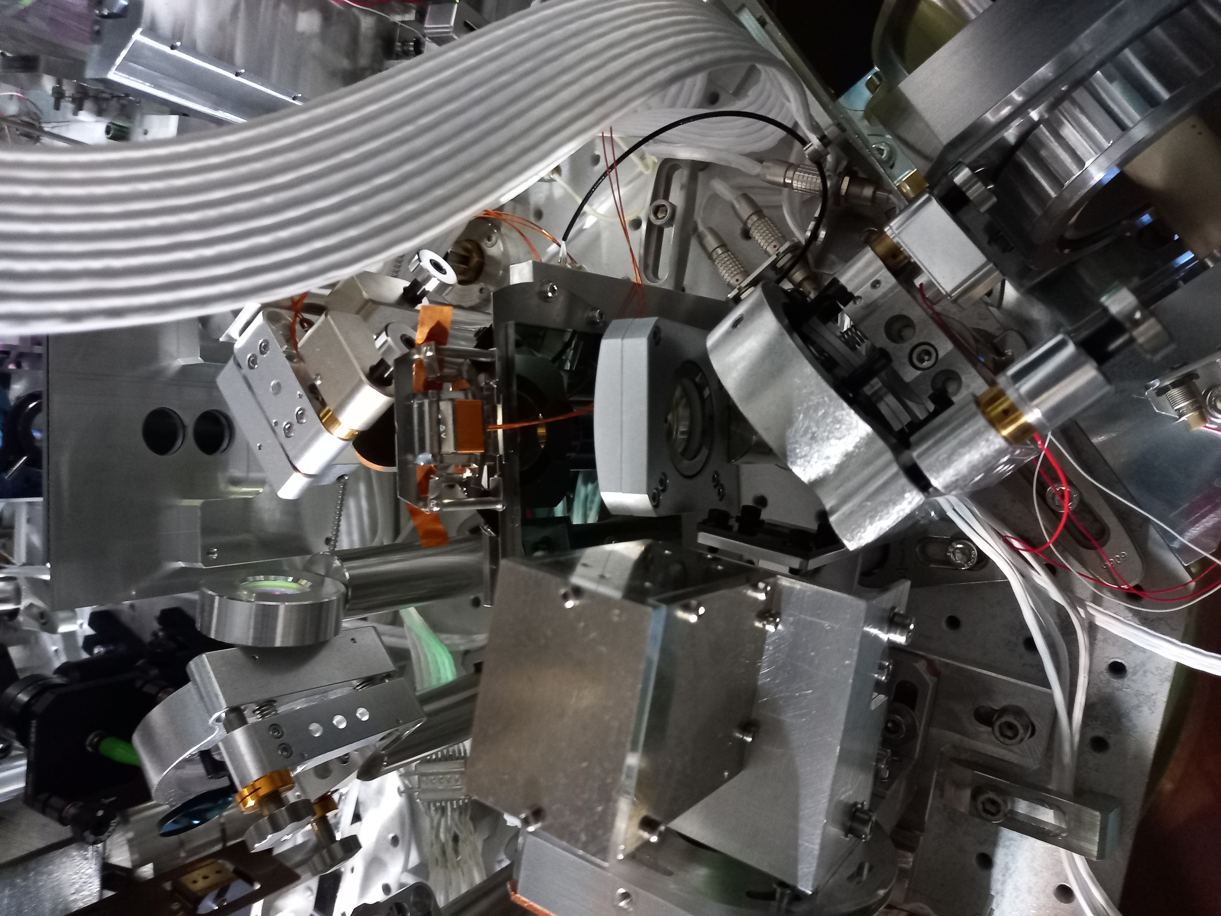
After this, we installed four irises along the auxiliary beam to have alignment references:
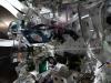
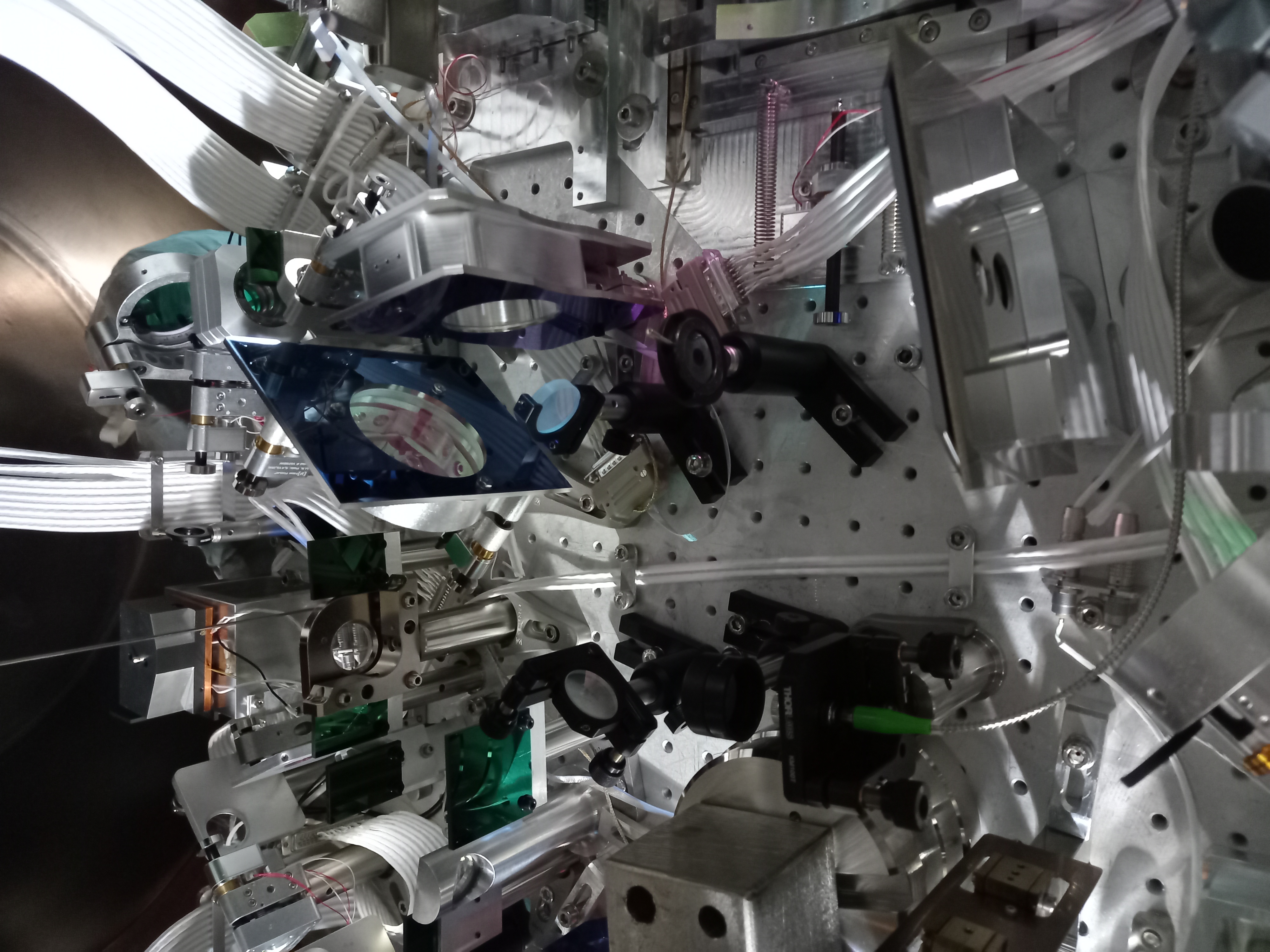
* One iris is placed before the B1/B5 diaphragm (Fig.1)
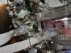
* One iris is placed between the single hole diaphragm and the SDB1_M3 mirror (Fig.2)
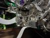
* One iris is placed before the SDB1_Mmot1 mirror, and one right after the OMC reflection (Fig.3)
Before installating the new half waveplate, we had to displace the clamping fork of the SDB1_M1 mirror to make room on the bench. To this purpose we installed some temporary clamps around the column of this mirror. After each step of this operation we checked the alignmetn on the irises and did not observe any change in the alignment. We managed to displace the clamping fork to the foreseen location. The very last step was to remove the last temporary clamp. After doing this, we noticed a change in the alignment references. But we suspect that this is the collimator alignment of the auxiliary laser that changed after we touched incidentally the fiber. To check this hypothesis we did the following tests:
* we reinstalled the last temporary clamp. This did not produce any change in the alignment ;
* we touch the rear side of the collimator, and this way we managed to realign the beam at the previous references.
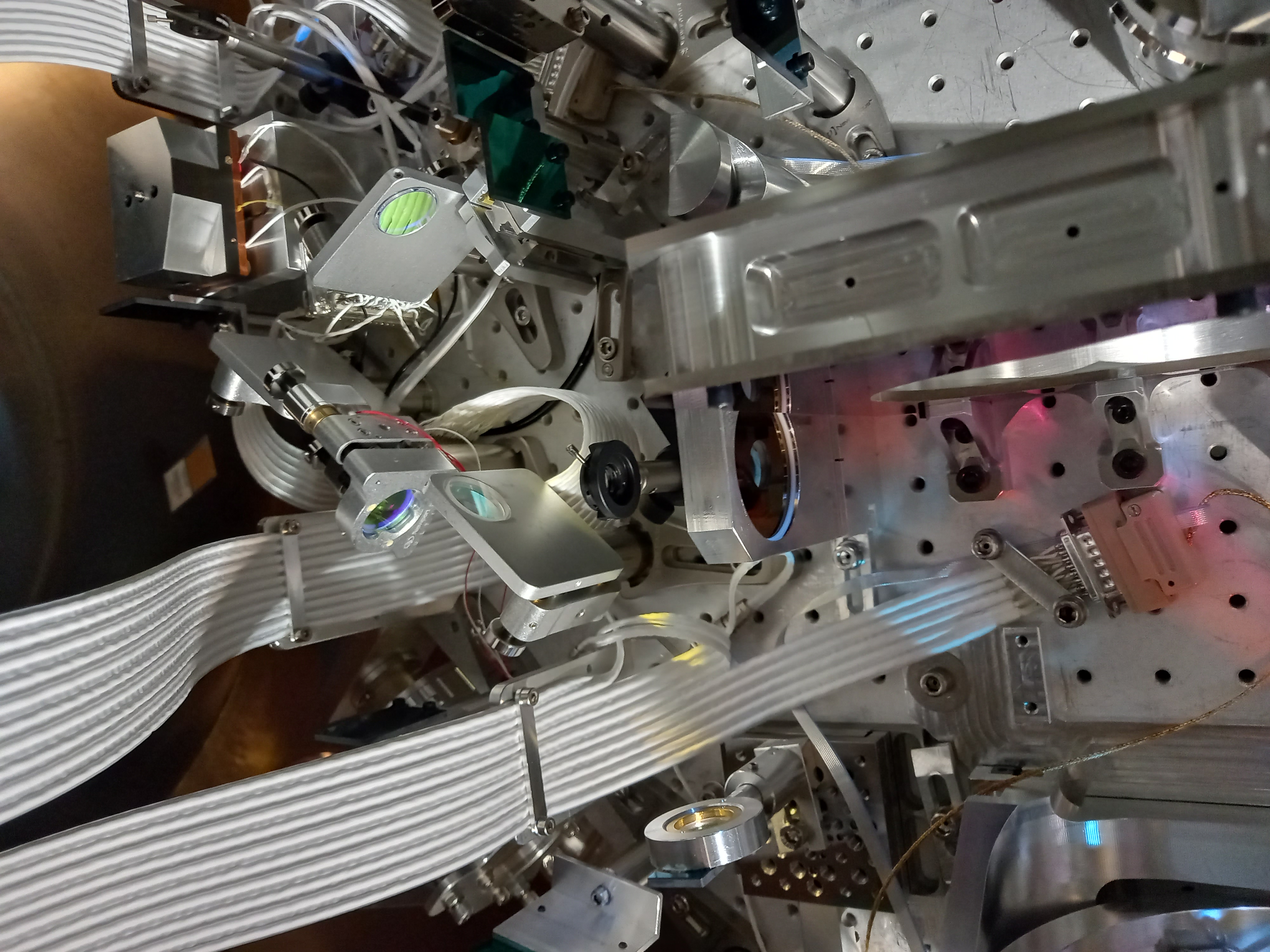
We weighted the new half wave plate including its mount, colunm and clamp: 552 g.
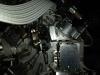
We then installed this half wave plate on the bench at the foreseen location (Fig.4 and Fig.5).
After installing the half wave plate, we added a temporary reflective mirror (with no wedge) using an adaptor, on the waveplate rotation stage. This mirror was used to tune the tilt angle of the waveplate that was applied to send the mirror reflection towards a new glass beam dump. The glass beam dump was installed between the dichroic mirror and the parabolic mirror MMT_M2 (a picture of the glass beam dump will be posted later).
The glass beam dump, including its mount, colunm and clamp was weighted: 223 g.
We checked by looking through the Hartmann beam lens that the new beam dump is not hiding the MMT_M2 mirror.
Finally we plugged the new waveplate rotation stage to its cable and tested it successfully (with 10 steps in one direction and -10 steps in the other direction).
Tomorrow we still have to perform the following tasks:
* measurement of the power before and after the FI
* Dismounting of the alignment references and auxiliary laser and fixing the temporary displaced cables
* Adjusting the bench weight, and rebalance the bench to suspend it.
* Check the position of the beam dump with respect to the Hartmann beam with the bench suspended and controlled in air.
* Check with the NI single bounce beam that the general alignemnt of the bench has been preserved.