Doing a PRCL offset scan to minimize the frequency to amplitude coupling at the input of the interferometer: https://git.ligo.org/virgo/commissioning/commissioning-tasks/-/issues/12
Starting after the calibration measurements between 16:00 and 16:15 UTC. The steps are done at a speed of ~1 unit of PRCL per 20 second.
16:22 UTC (5min) PRCL_SET = 1.0
16:28 UTC (5min) PRCL_SET = 2.0
16:35 UTC (5min) PRCL_SET = 4.0
16:42 UTC (5min) PRCL_SET = 6.0
16:51 UTC (5min) PRCL_SET = 0.0
17:00 UTC (5min) PRCL_SET = 6.5
17:07 UTC (5min) PRCL_SET = 6.2
17:16 UTC (5min) PRCL_SET = 12 - interupted by unlock just after 17:18:40 UTC
just after reaching LN3
18:10 UTC (5min) PRCL_SET = -6.0
18:17 UTC (5min) PRCL_SET = 0.0
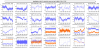
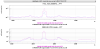
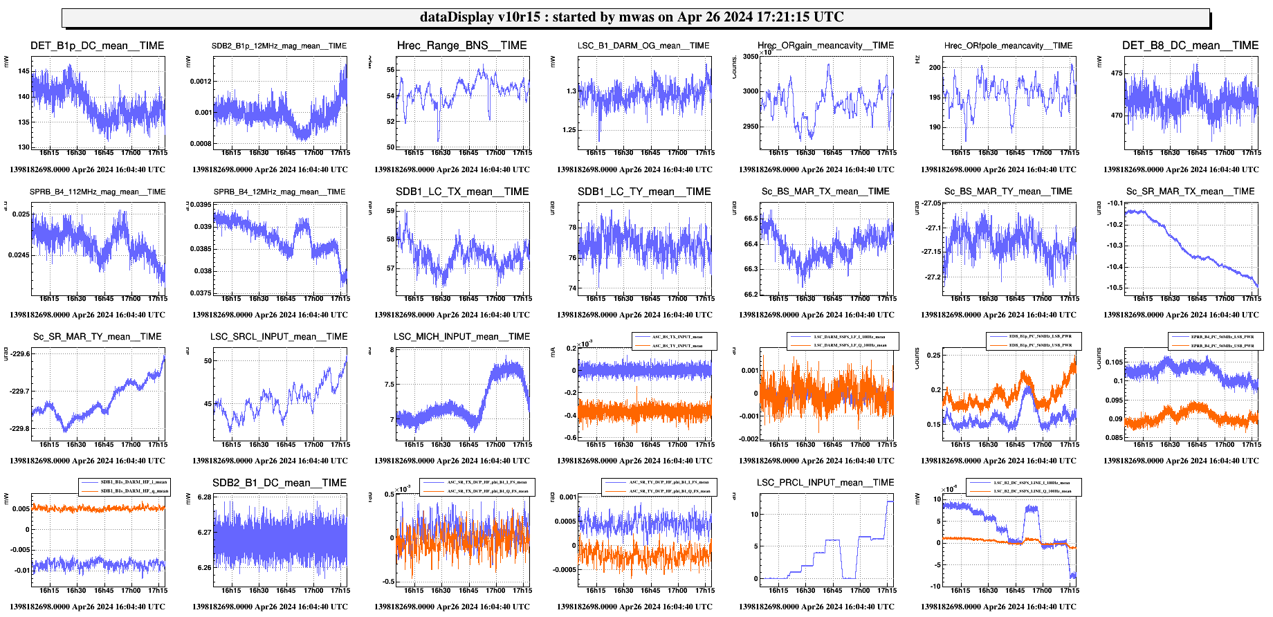
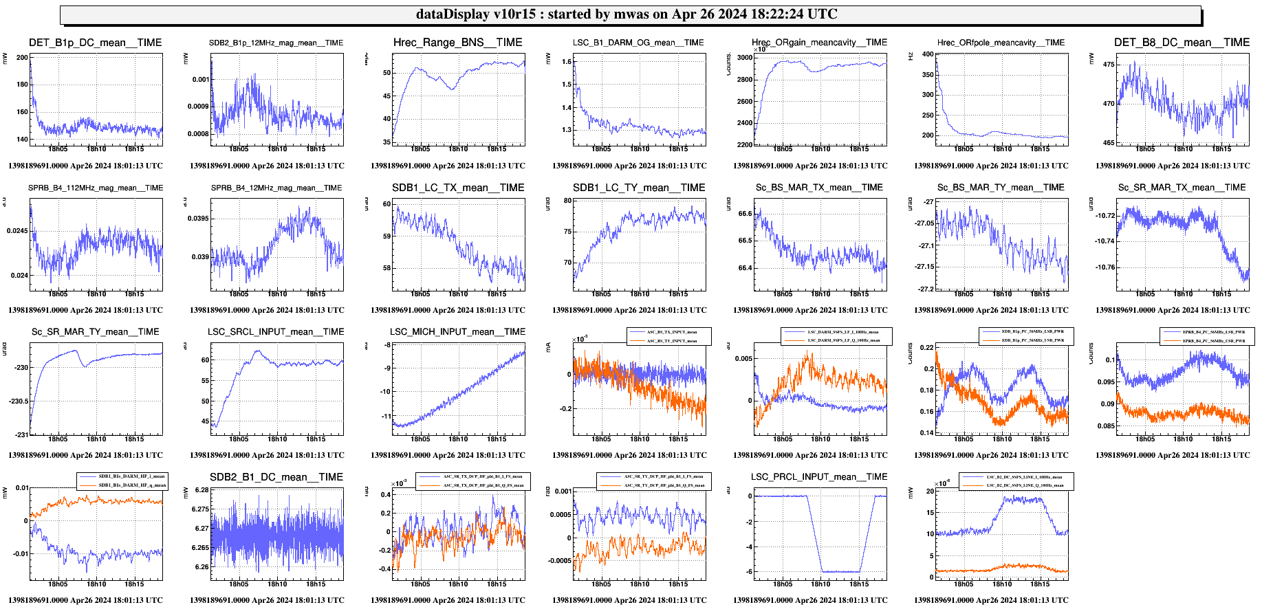
Figure 1 summarizes the scan done up to the unlock, PRCL_SET ~ 6 correspond to zeroing the frequency to amplitude conversion by the interferometer as seen on B2. It also shows that adding the offset in PRCL reduces the 6MHz gain as seen on B4 12MHz by 2%.
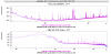
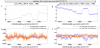
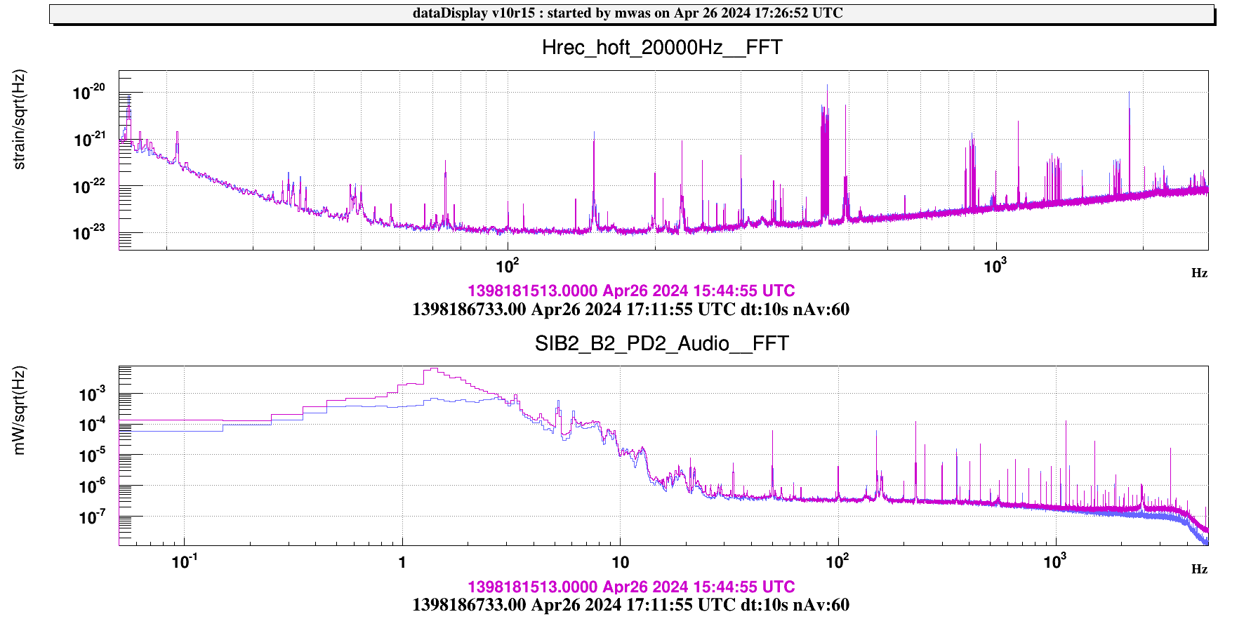
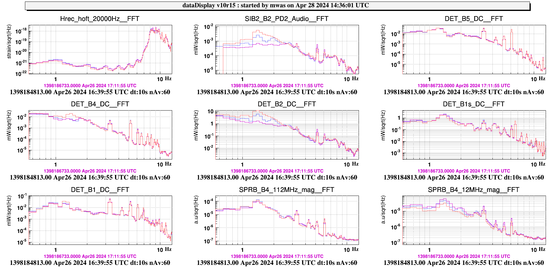
Figure 2 compares the time with the frequency noise coupling to minimized (blue) to the normal situation (purple). The B2 noise is 10 times lower between 1Hz and 3Hz, and it is also lower above 1kHz where the frequency noise is dominant. In between B2 is dominated by the pole at ~500Hz noise, subtracting it using B5 or B4 could reveal more clearly the improvement in coupling of frequency noise to B2 at other frequencies. There is no wideband impact on the h(t) noise.
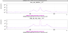
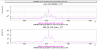
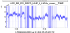
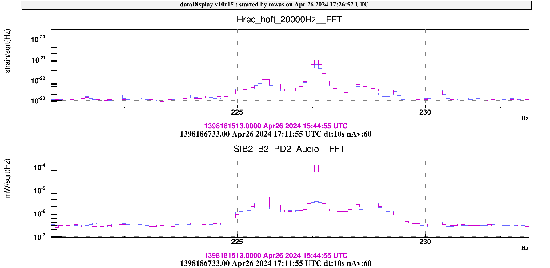
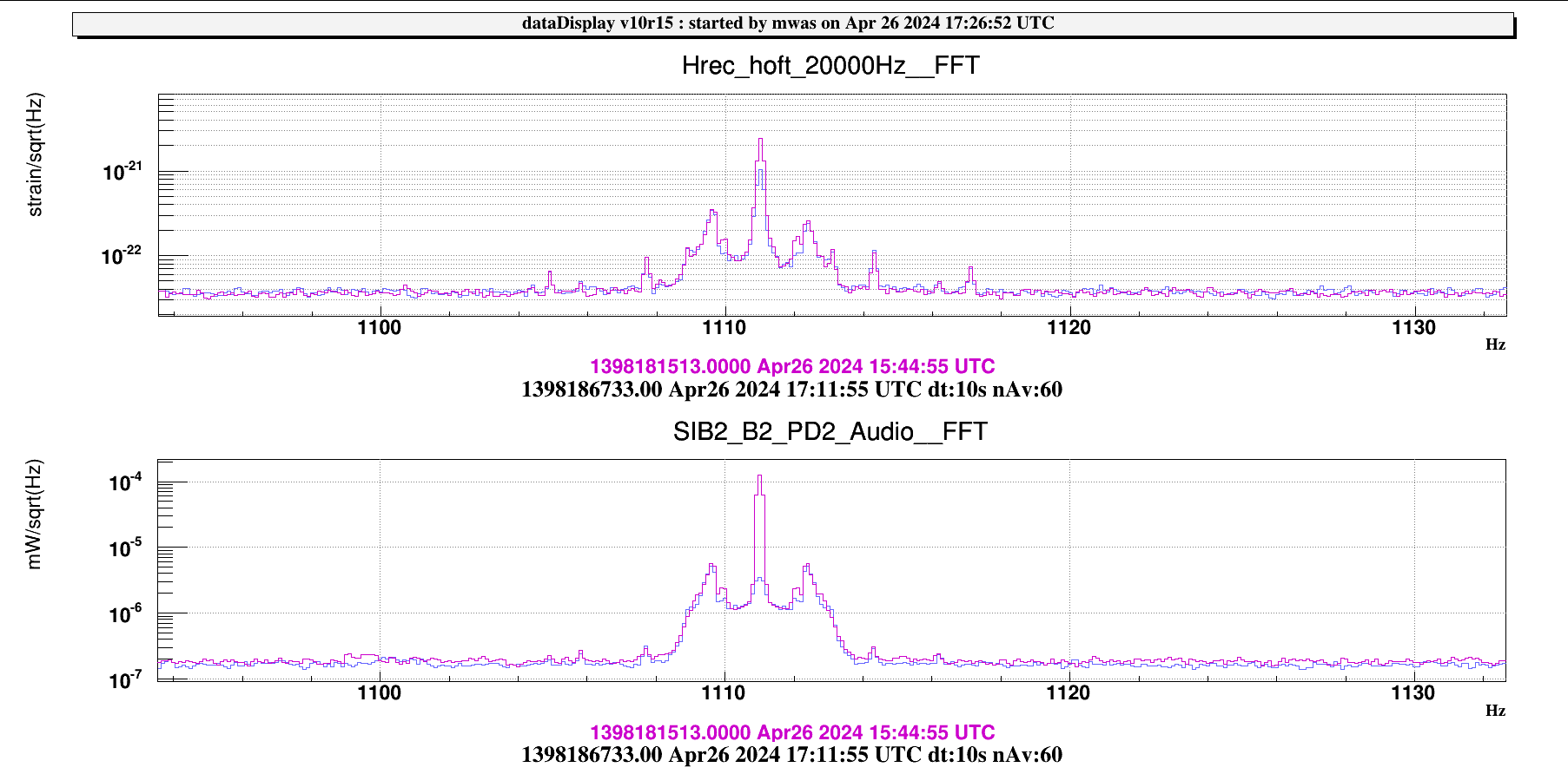
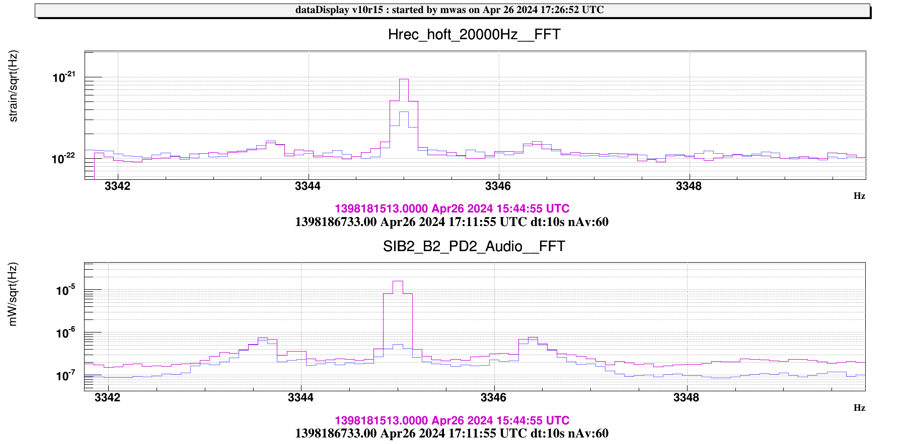
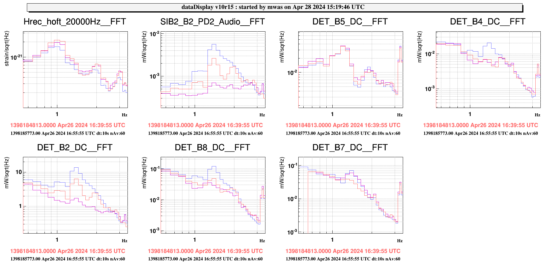
Figure 3, 4, 5 show that the frequency noise lines (227Hz, 1111Hz and 3345Hz) are a factor ~30 lower on B2, and about a factor 2 lower in h(t).
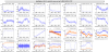
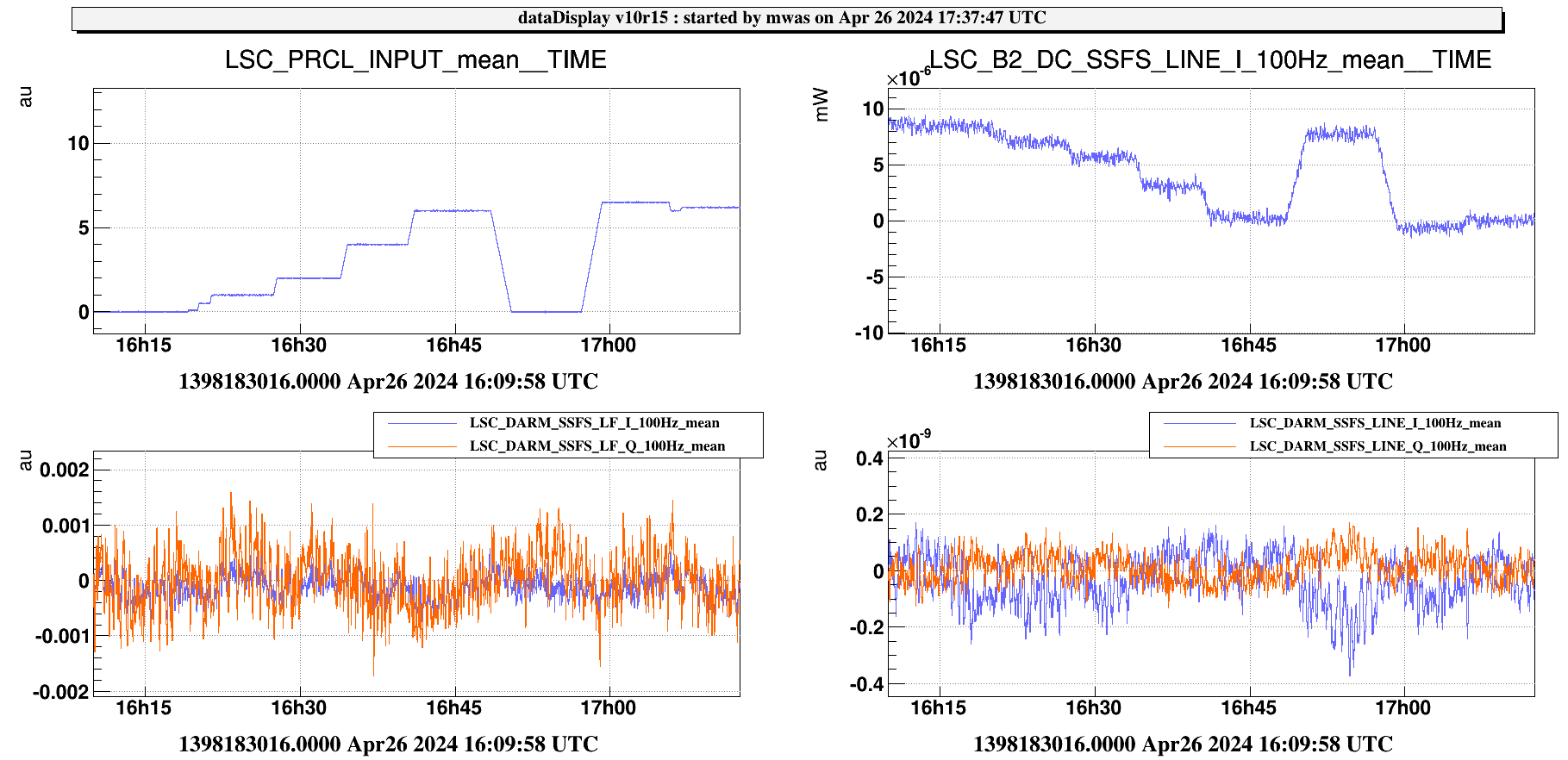
Figure 6 my impression is that the coupling of frequency noise to h(t) becomes lower because for SSFS_LF the I and Q quadratures become more overlapped, so the BS TY minimizes both at the same time, and for SSFS_LINE the I and Q quadratures (that are very correlated), become of equal magnitude but opposite sign.
I wonder what it means that the frequency to amplitude noise coupling is zeroed, while the sideband gain decreases. Does it mean that the sidebands are not well tuned to the length of PRCL, and we need to choose to have carrier well resonant or sidebands well resonant?
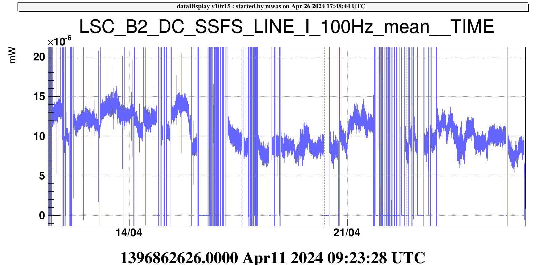
Figure 7 the coupling of frequency noise to B2 has been quite stable since the beginning of the run
Figure 8 shows the PRCL offset scan done just after the unlock. This scan went with the same magnitude but in the wrong direction for the frequency to B2 noise coupling, and this time it increased the B4 12MHz mag signal by ~1.3%. So it points towards the current working point being in between being good for sideband gain and being good for the frequency to amplitude coupling at the interferometer input. That would intuitively make sense if the sideband frequency doesn't match the PRCL length, and the RF error signal that is the between sideband and carrier finds a working point in between being good for the carrier and for the sideband.