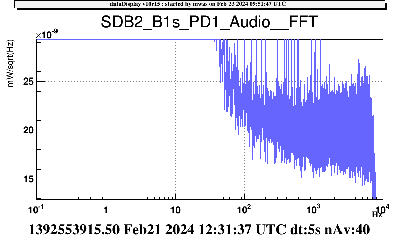
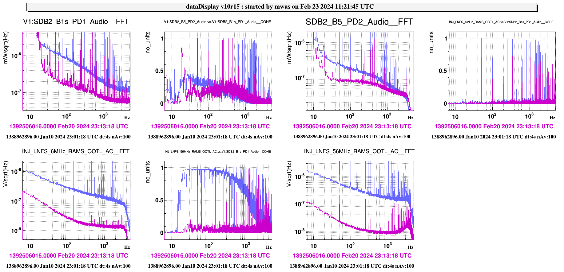
The B1s photodiode has been replaced by one that doesn't have a large electronic noise on Feb 20.
Figure 1 shows that the new electronic noise level is at 2e-8 mW/rtHz.
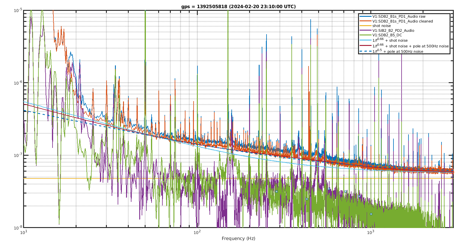
Figure 2 shows the B1s photodiode in LN3. This can be compared to the previous analysis done a month ago: https://logbook.virgo-gw.eu/virgo/?r=63036.
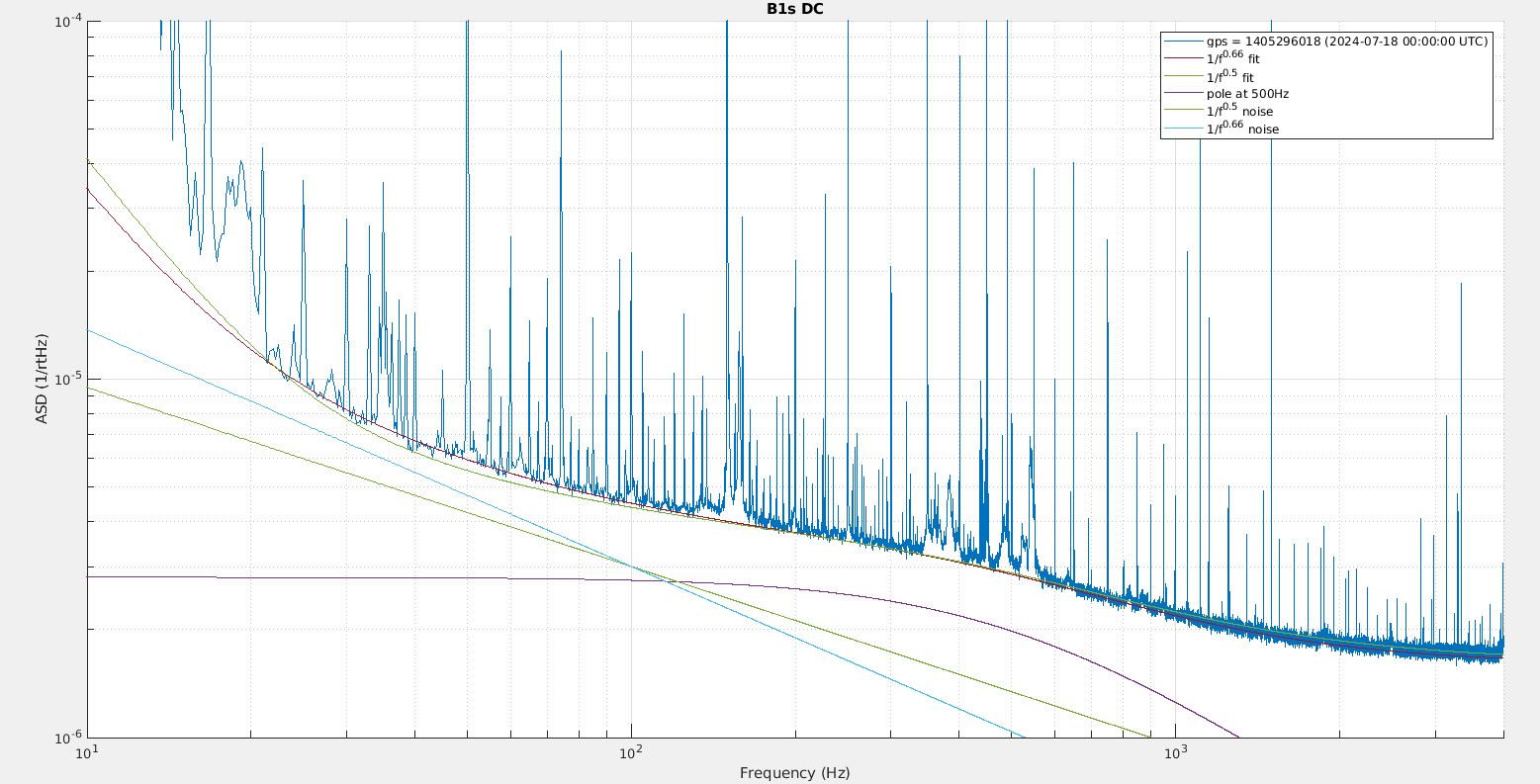
With the lower sensing noise the noise that has a shape of a pole at ~500Hz becomes more clearly visible on B1s. It is coherent with B5 (and B4), and one can use B5 to subtract it. The result is the red line on the figure. Trying to fit the remaining noise with just a noise of the 1/f^0.66 plus some frequency independent noise (shot noise + electronic noise) yields the cyan line, which doesn't follow well the measured noise.
A better fit can be achieved by adding to the 1/f^0.66 noise a noise shaped as a ~500Hz pole, which would assume that the the ~500Hz pole noise is not well subtracted and that there is a second component of it at 7e-8 mW/rtHz that is not coherent with the one visible on B5. Another way to achieve a good fit is to use a 1/f^0.5 noise instead of the 1/f^0.66 noise, note that a 1/f^0.5 slope is not compatible with the measured mystery noise slope. https://logbook.virgo-gw.eu/virgo/?r=63220.
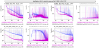
Figure 3 compares the current situation (purple) with the one before the RAMS servo active loop was closed. The noise on B1s at 100Hz has reduced by a factor ~5 since then thanks to the RAMS servo. The OOTL monitoring of the 56MHz RAMS has reduced by a factor 20, so in principle the 56MHz RAM is factor below what we measured on B1s right now. This is also consisten with the ~5% coherence between B1s and 56MHz OOTL RAMS signal. This conclusion assumes that OOTL RAMS is indeed an out-of-loop signal.
So there is an excess noise optical on B1s, and it doesn't seem to be easily explained by RAMS or pure mystery 1/f^0.66 noise, nor by the ~500H pole noise.

