Reports 1-1 of 1 Clear search Modify search
AdV-INJ (Electro optical modulation system (EOM))
nocera - 22:36 Wednesday 17 January 2024 (63004) Print this report
RAMS servo commissioning

D. Bersanetti, B. Montanari, F. Nocera, P. Spinicelli

Today has been completely devoted to the (re)installation and commissioning of the RAMS system for the 6 and 56 MHz sideband.

We decided to make things in steps and to relock up to at least Low Noise 2 after each step.
As already done last week (62924) we arranged things so that, once the phase change had been accounted for, there was no need to modify of tune any lock parameters but the LNFS output levels that are now set, for both frequencies, to +15 dBm..

At the beginning we started relocking with only the 6 MHZ RAMS servo unit on the modulation path with the loop open (no servo on the 56).
It was difficult to reach Low Noise 2 for reasons independent of our doing. We finally managed to get to LN2 around the time of the Daily Meeting.
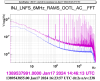
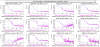
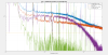
Shortly before 4 pm local time we closed the RAMS servo loop and started to relock again.

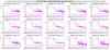
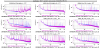
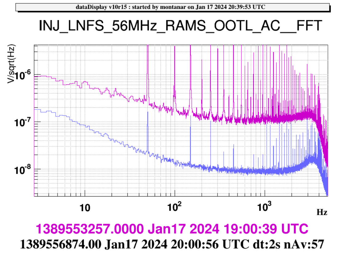
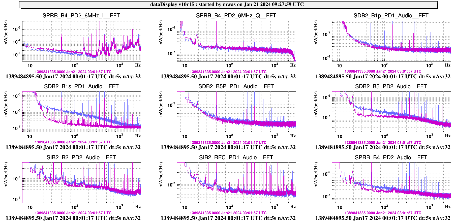
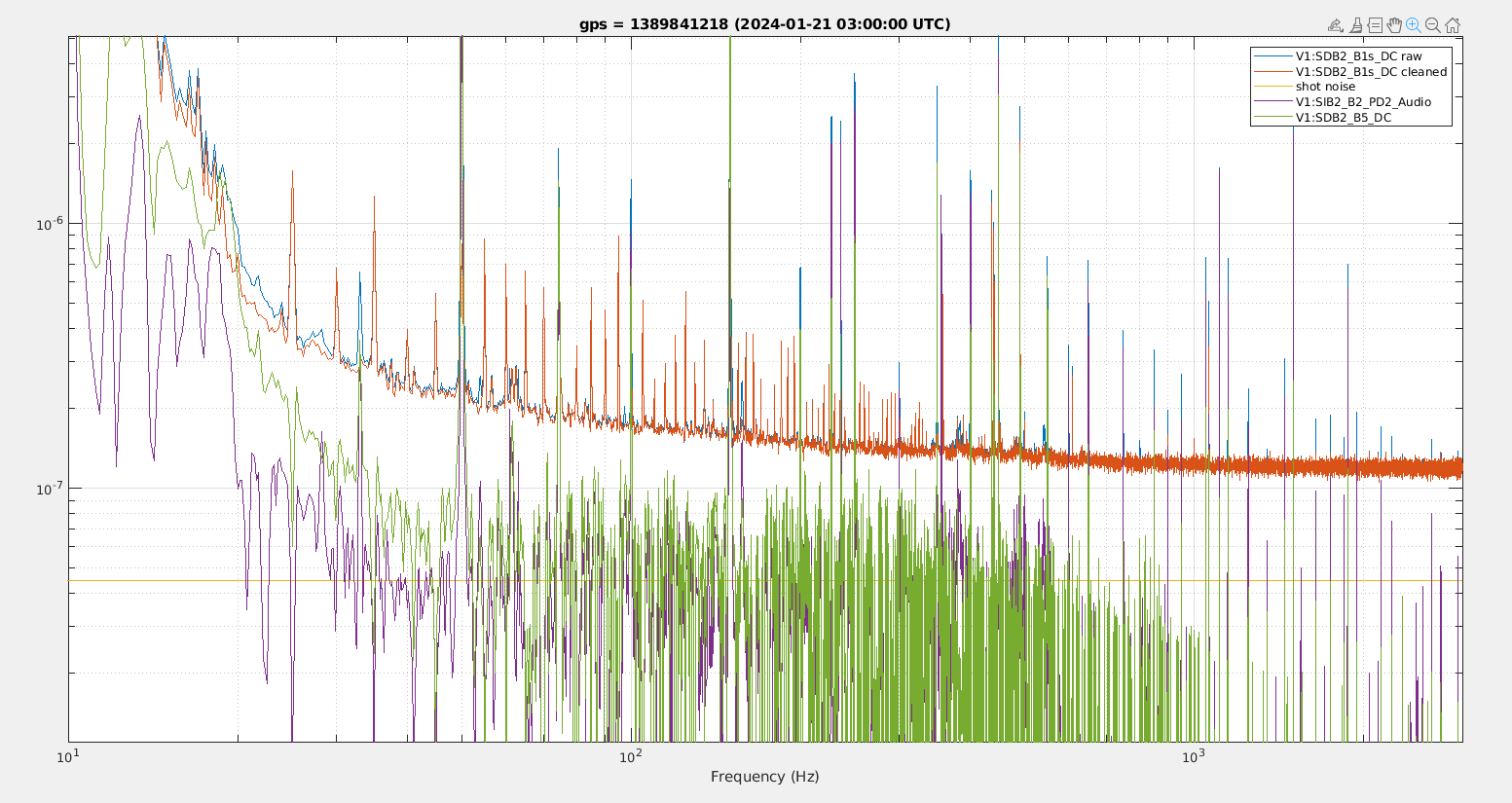
In fig.1 it is possible to see the performance of the loop (on/off).

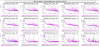
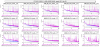
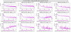
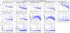
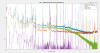
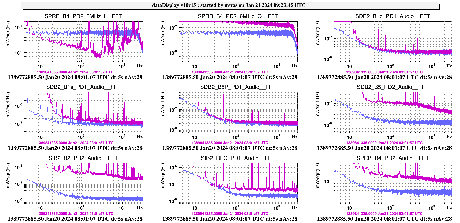
We then repeated exactly the same procedure for the 56 MHz as well. The results are visible in fig.2. When the 56 loop was open, a clearly visible oscillation just above 1 Hz appeared on many signals, but in the end it went away exactly as it had appeared. Details will probably follow in a separate entry.

Finally, here is a list of the time windows you can use if you want to explore further data available in each of the configuration used

start time stop time ITF State 6 MHz servo 56 MHz servo
1389537084 1389538743 LN2 in, loop Open bypassed
1389542455 1389545263 LN3 in, loop Closed bypassed
1389550533 1389553854 LN2 in, loop Closed in, loop Open
1389557880 -- LN3 in, loop Closed in, loop Closed

We leave both servoes on their respective modulation paths with the loops closed.

Images attached to this report
Comments to this report:
masserot - 23:00 Wednesday 17 January 2024 (63005) Print this report

The following plots  compares 2  lTF's lock at LOW_NOISE_3:

  • purple at 2024-01-17-08h00 without any RAM servo loop
  • blue  at 2024-01-17-20h40 with the 6MHz and 56MHz RAMS servo loops closes

This plot ( zoom 5Hz-5KHz, zoom 10Hz-1KHz) compares the RFC, B2, B4, B7, B8, B5, B1s, B1p and B1 Audio channels without and with the RAMS loops closed

This plot ( zoom ) compares the ITF error signals without and with the RAMS loops closed

Images attached to this comment
mwas - 11:38 Sunday 21 January 2024 (63036) Print this report

A few comments on what we can see now that the RAMS noise is nicely reduced by the new servo.

Figure 1 shows the difference in spectra with the RAMS loop closed (purple), and without it (blue). On B1s we see the RAM nicely removed, on B5, B4 and B2 it is also reduced, and reveals another noise of a different origin that has a shape of a pole at ~500Hz.

Figure 2 shows that none of the cleaner audio channels shows any very interesting coherence with B1, appart from B5 below 20Hz which would be interesting to study further. But it shows that the newly revealed noise in B5, B4 and B2 is common between these 3 output ports.

Figure 3 shows how B2 can be used to remove that common noise from B5. The result on B5 it still a factor 2 above shot noise.

Figure 4 shows how B5 can be used to remove the common noise from B2. The result is a factor 3 above shot noise, it might have a significant contribution of frequency noise, the 227.1Hz line is a factor 500 above this noise level (for 5s long FFTs), and it is also the case for the SSFS Q noise compared to the SSFS I line at 227.1Hz (see figure 7).

Figure 5 shows B1s. After removing the RAM noise, there is a factor 2-3 more noise than expected just from shot noise.

Figure 6 compares the PD spectrum with the RAM servo enabled, and a time without a laser beam (IMC unlocked). It shows that on B1s at 2-3kHz we are actualy limited by PD electronic noise, which is a factor few higher than for other photodiodes. On B1p PD1 the spectrum is limited by electronic noise above 20Hz, as there is 100 times less power on that photodiode than on B1s. And B4 PD2 6MHz I, the extra noise visible since last week, is actually a factor few below the PD electronic noise, so it may not be a very relevant issue, but it is still worth to follow this up to understand why the 6MHz I signal from the same photodiode is different on SPRB and in the SSFS process.

It would be interesting to replace B1s with a photodiode with less electronic noise, and check if the 5Hz comb on B1s is due to some LED blinking inside the electronic tank or some similar issue.

Figure 8 shows B4 after subtracting from it the coherent noise with B5. The resulting noise floor is flat, and a factor 1.5 above shot noise, it is also a factor 3 above the PD electronic noise.

Images attached to this comment
Search Help
×

Warning

Error

The present report has been modified outside this window. Please check for its integrity in the main page.

Refreshing this page will move this report into drafts.

×