1/ Morning activity: the morning was dedicated to the alignment of the OMC under vacuum using the NI single bounce beam.
We performed the alignment of the OMC in single bounce with the offsets from B5 QD2 quadrants removed.
Closed angular loops of SDB1 at nominal setpoints used in NI single bounce under vacuum (reference checked on Dec 26th). We had to rebalance the bench with the motorized counter weight :
BENCH_TZ : -10000 steps, BENCH_TX : +10000 steps
Closed SDB2 LC and SDB2 SBE loops.
After the vacuum team reopened the valves (around 08h50 utc) the B1p beam was visible on the camera. We could then reactivate the DET_MAIN node in the automation.
Going to NI single bounce, PR misaligned further to get rid of the ghost beam on the B1p camera.
Closing B5 beam drift control at 09h11 utc.Open OMC slow shutter at 09h14 utc.
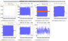
OMC locked at 09h33m20 utc on carrier TEM00. When PZT engaged, we noticed very large noise. We reduced the PZT gain from 6000 to 4000 at 09h30m09 utc. This allowed to reduce the corrections and the noise as shown on Fig.1. Reduced further the gain to 3000 at 09h44m30 utc.
We then improved the OMC alignment by acting on the picomotors of the two folding mirrors placed in front of the OMC.
Use SDB1 high bandwidth control from 10h15m45 utc.
OMC scan starting at 10h28m40 - 10h32m23 utc: TEM00 : 9 uW ; order 1 (mostly horizontal) : 0.5 uW ; order 2: 0.16 uW (piedestal removed).
OMC relocked on carrier TEM00 at 10h37m40 utc.
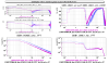
Measurement of OMC length control OLTF:
Start injecting noise (amp 1e-4) in OMC error signal at 10h53m40.
Double the noise amplitude at 10h59m49 utc. Collecting data for 7 min. The measured OLTF is shown on FIg.2 The ugf is found between 3.2 and 3.3 Hz (with PZT filter gain at 3000)
Stop noise injection at 11h08m07 utc.
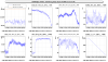
Checking B1_PD3 alignment:
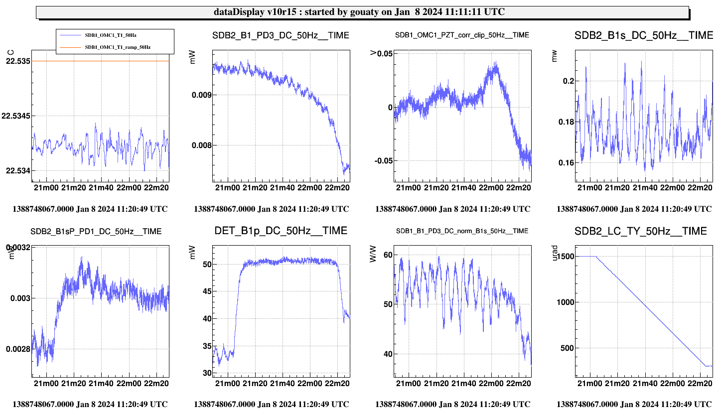
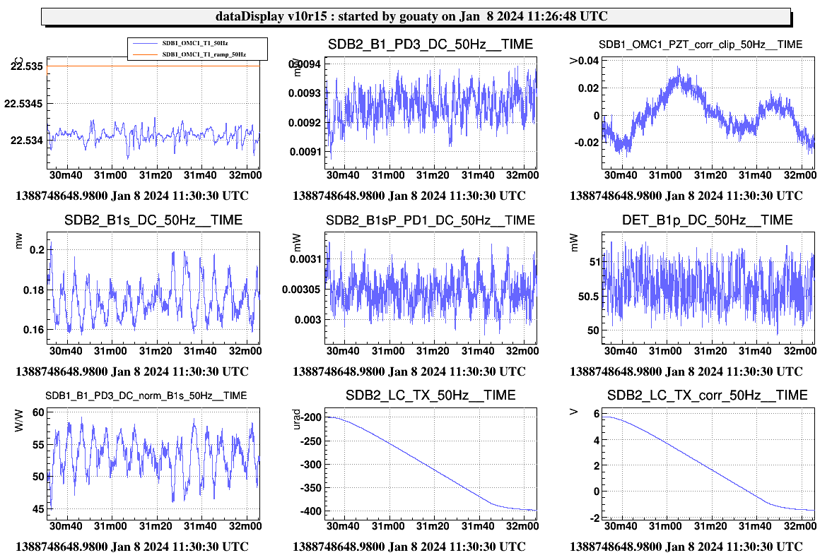
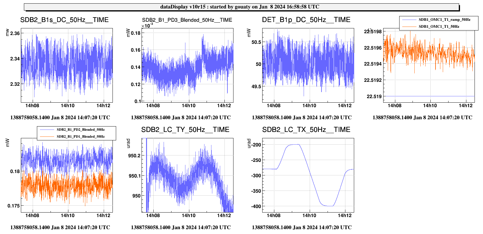
SDB2 TY nominal = 950 urad. TY scan from 1500 to 300 urad (see Fig.3). B1_PD3 power has a slowly decreasing trend from 1500 to about 500 urad and then seems to drop at lower angle. The slow trend looks more like the effect of the change of angle of incidence on the beam splitter transmission than a real problem of alignment.
SDB2 TX nominal = -280 urad. TX scan from -200 to -400 urad (see Fig.4) > no significant impact on B1_PD3 power.
Aligning B1 beam on its camera. Using data from Dec 26 (single bounce) as reference : B1 FitPosX = 26 urad ; B1 FitPosY = -177 urad. Performed -1150 steps on B1_M1_H and +500 steps on B1_M1_V to center the beam on the camera. During this alignment we noticed a little change in power on B1_PD3 which seems again consistent with the effect of variation of polarization transmission as a function of the angle of incidence.
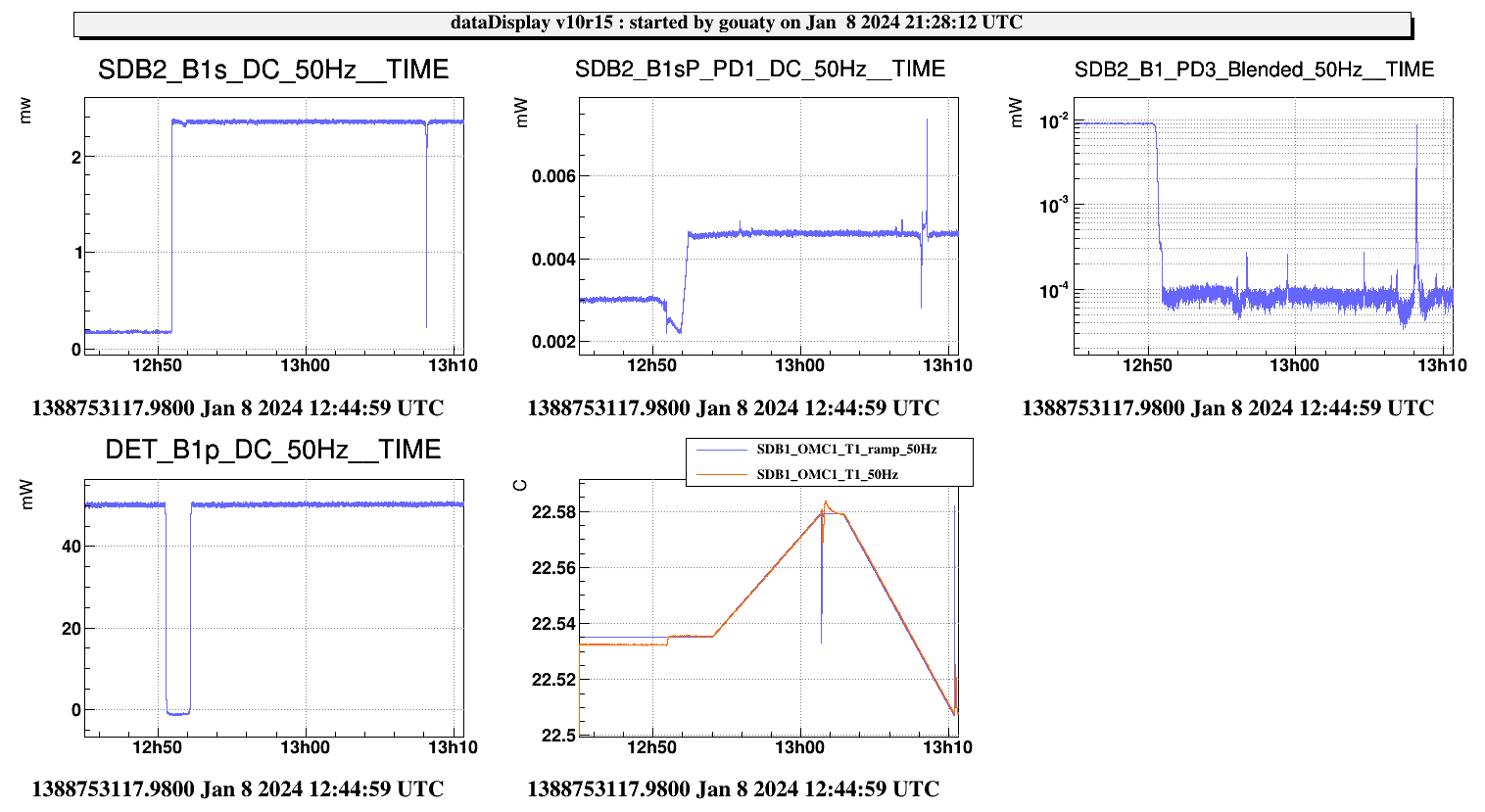
Start OMC scan at 12h54m00 utc - 13h09 (see Fig.5)
TEM00 carrier : 9.1 uW
order 1: 0.20 uW > 2.2% of misalignment defect.
order 2: 0.18 uW > about 2% mode mismatch.
Tuning of polarization: we performed about -250 steps with OMC north waveplate to minimize B1sP with OMC locked on carrier TEM00 (see Fig.6).
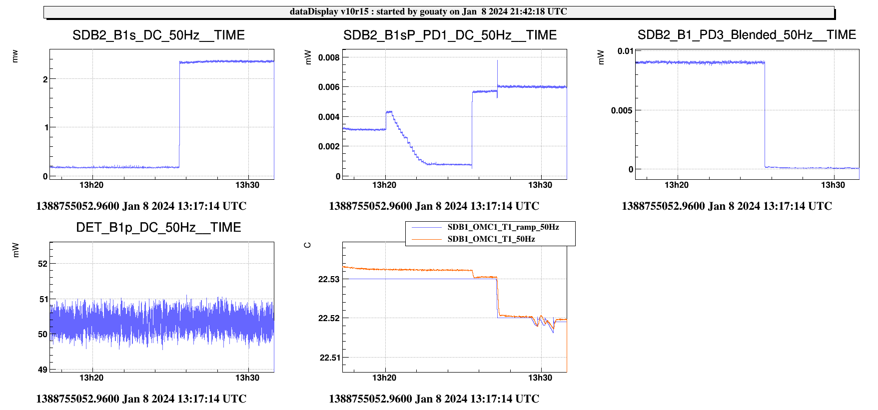
OMC locked on SB 56 MHz TEM00 at 13h35m10 utc, with B1 PD1/2 shutters opened (see Fig.7).
Get ~0.07 uW on B1_PD3 (offset substracted). Compared to 0.36 mW on B1_DC. Ratio B1/B1_PD3 ~ 5000. Thus, the 9 uW obtained on B1_PD3 with the carrier TEM00, corresponds to about 45 mW on B1_DC. Therefore it seems that the PD1/PD2 photodiodes are reasonably aligned.
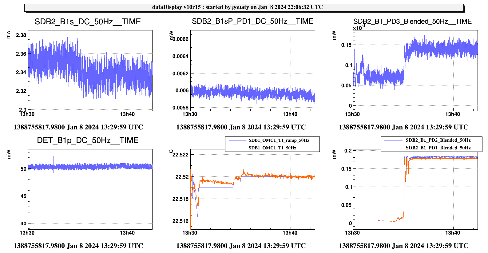
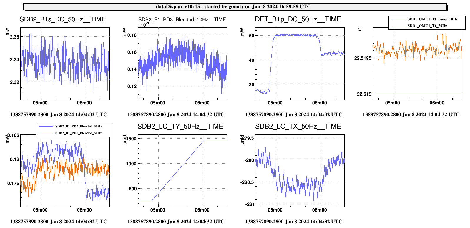
We perfomed 900 steps on B1_M2_H, and then performed an angular scan of SDB2 in TY (Fig.8) and in TX (Fig.9). The B1 photodiodes seem to be well centered.
2/ Afternoon activity: Recovery of DC readout
ITF loked in CARM NULL. Scanning the OMC temperature from 15h23m10 utc, with DARM offset -0.17. Given that the power on the carrier TEM00 barely reach 5 uW, we decide to increase the DARM offset to -0.24. This allows to get about 10 uW on the carrier TEM00 on B1_PD3.
We also update the OMC locking threshold on B1x_DC_DARM_norm_prod at 450 (instead of 900) to be able to lock on a smaller power.
Locked OMC on carrier TEM00, and checked B1_PD3 centering by scanning the angular position of the mirror SDB2_B1_M4: The beam was inside the plateau but not perfectly centered. Centering improved with -1000 steps on B1_M4_H and +7000 steps on B1_M4_V.
Locking the OMC with the automation (hand off commented by Diego): OMC successfully locked at 16h07m30 utc.
ITF unlocked during hand off at 16h23m39 utc. The B1_PD3 power was getting too high.
We update the B1_PD3 safety thresholds to account for the smaller power on this photodiode:
* in DET_MAIN, max_power_B1_PD3 divided by a factor 5: max_power_B1_PD3 = 0.06.
* Updated threshold for triggering the fast shutter : ACL_RELAY_CH B1_PD3_DC_saturation au SAMP_FREQ 0 2 -2 B1_PD3_DC 0.1 0.04 >=
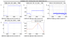
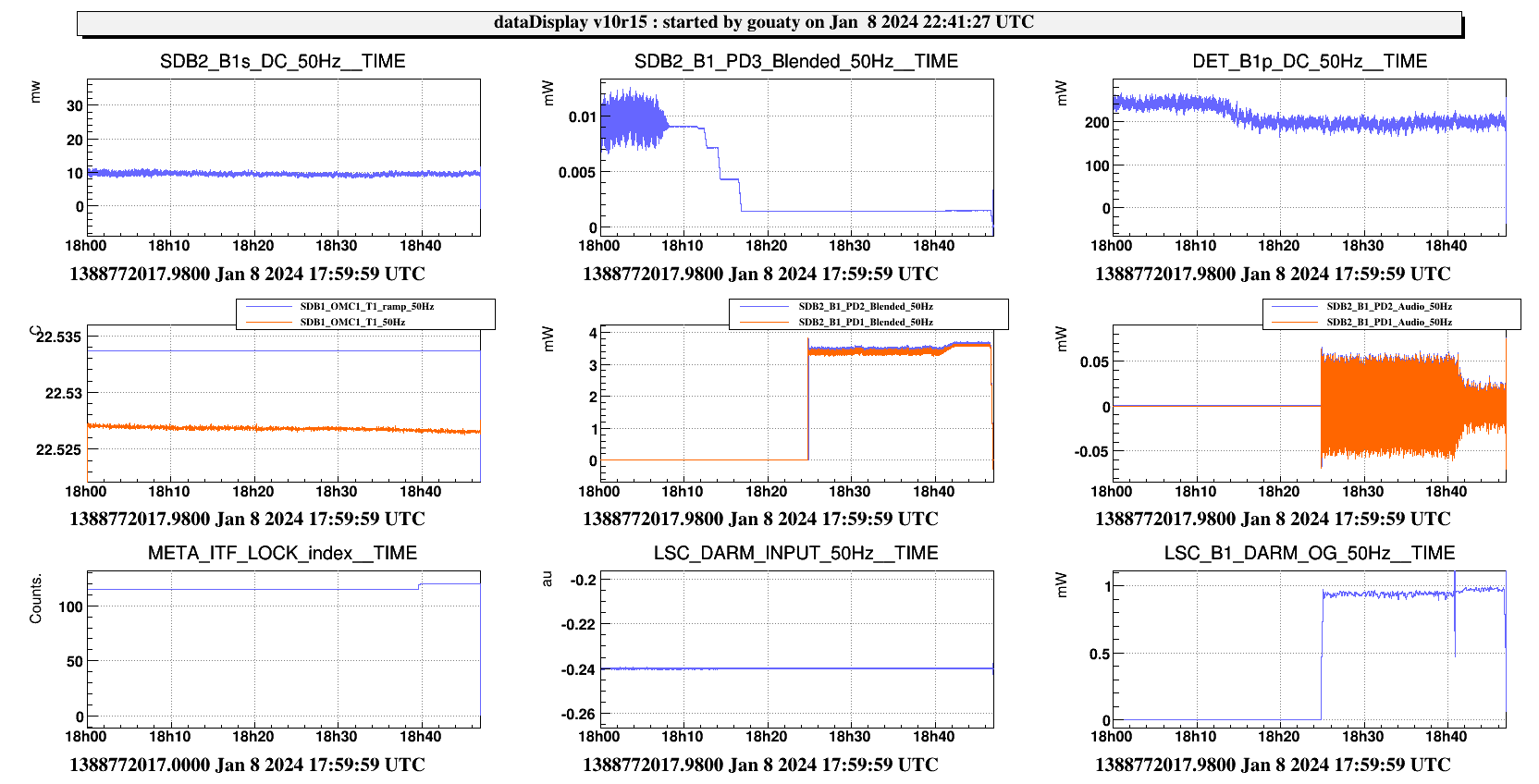
Successful hand off of DARM to B1_PD3 at 18h08m20 utc (see Fig.10)
Opening manually the B1 photodiodes at 18h24 utc.
Successful hand off from B1_PD3 to B1_DC at 18h40 utc, with 7.2 mW on B1_DC.
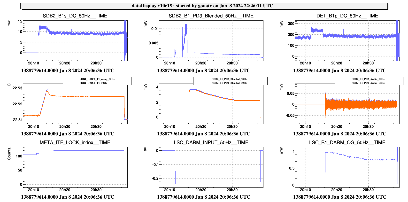
The automation was successfully tested up to the hand off to B1_DC around 20h18 (Fig.11). Then the power on B1_DC was adjusted manually to reach the standard 4.45 mW.
ITF unlocked and it was not possible to relock to DC readout by the end of the shift.
Still pending:
* Test the automation up to the reduction of the B1_DC power to 4.45 mW
* check the B5_QD2 offsets for the OMC alignment in DC readout.
* Recover Low Noise 3.


