To my knowledge the B5 port of the interferometer is the only one where we can try to measure the polarization of the light resonating in the interferometer. On B1p/B1s and on B2 there is a Faraday isolator on the path to the the photodiode that will reject any P-pol light, and on B4 we don't have a polarizer sending light onto a photodiode. On B5 there are two photodiodes, one looking at S-polarized light and the other looking at P-polarized light, and there is no Faraday on the B5 beam path. Unfortunately the B5 p-polarized photodiode shutter is closed most of the time, but yesterday evening during a lock acquisition I have opened the shutter of it.
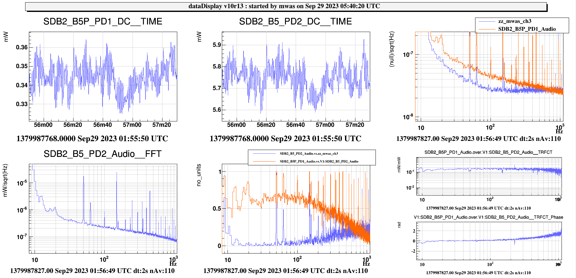
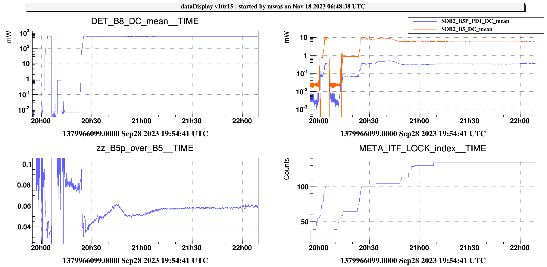
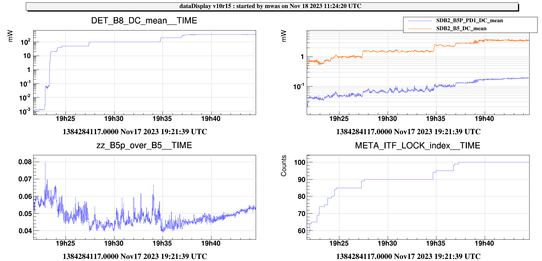
Figure 1. Shows the lock during the night, comparing B5 in P-pol and S-pol. The two are relatively coherent, with 60% coherence. From past tests, B5 S-pol is dominated by the 6MHz RAM. So it is not surprising that both photodiodes see the 6MHz RAM. What is a bit suprising is that the ratio of the DC powers is a factor 0.06 while the transfer function in the audio band is at 0.15. So there is discrepency of a factor ~2.5 between the polarization splitting at DC and in the Audio band. I don't have an explanation or interpretation of this. The measured transmission of S-polarized light by the polarizer coating is 730ppm, but the transmission might higher in practice if the angle of the polarizer is not well adjusted, but it is still surprising to see a power ratio that is a factor 100-200 higher. So this would point to a real content in the P-polarized light. However, the B5 beam path is not perfectly in the horizontal plane, due to the vertical wedge of BS (1mrad), and then on SDB1 the B5 beam is after the telescope several cm above the B1p beam before it is brought down using folding mirrors over a distance of ~50cm. So this might be causing a light polarization change.
The zz_mwas_ch3 channel is the B5 P-polarized signal with the S-pol PD subtracted with a weight of 0.15 to remove the 6MHz RAM contribution. This seems to work well between 10Hz and 100Hz, and at higher frequency it doesn't because of a phase difference (probably because B5 PD2 has an additional 8th order butterworth filter compared to B5P PD1). Nonetheless, between 10Hz and 100Hz there seems to be an extra 1/f contribution remaining after the subtraction of the 6MHz RAM.
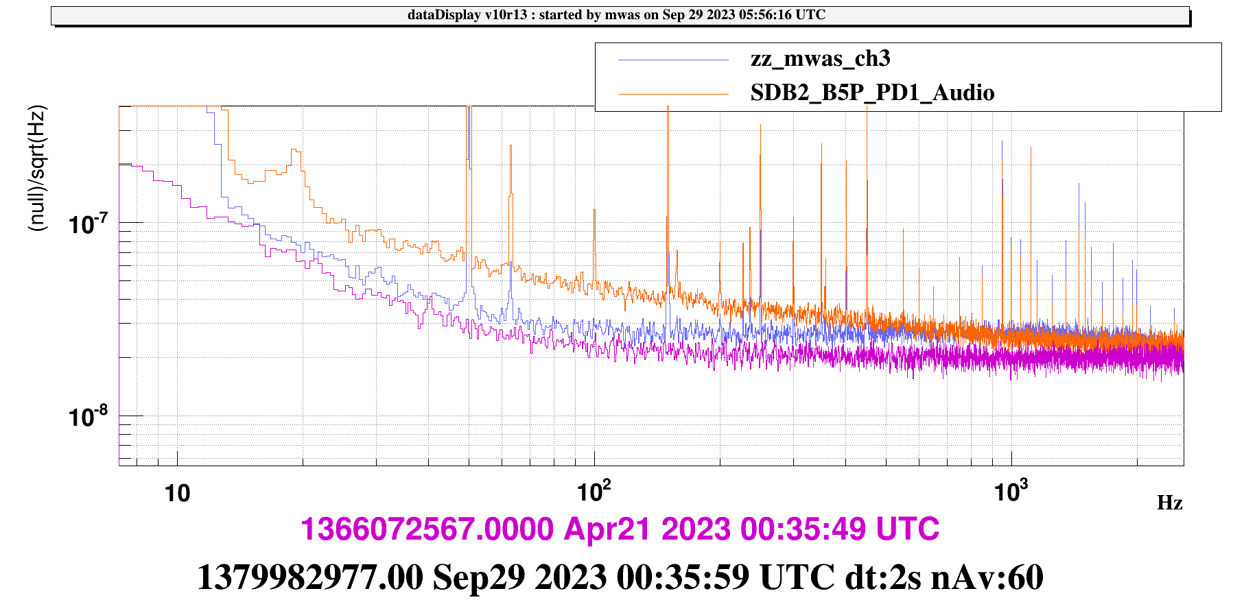
Figure 2 shows in purple B5P with the shutter closed, in red with the shutter open in LN3 and in blue B5P with the 6MHz RAM subtracted. After subtraction B5P looks similar to the electronic noise, so the 1/f noise doesn't look that interesting.
We can still use the B5P spectrum to derive an upper limit on the polarization fluctuations of the interferometer light. And it is 2.5e-8 mW/rtHz / 5.8mW = 4.3e-9 1/rtHz.
It would useful to check the calibration of B5 and B5P to understand if the discrepency by a factor 2.5 in their ratio is an artifact or a real measurement.
It would be useful to replace the B5P photodiode with one with a similar configuration as the B1 photodiodes, that have 3 times less electronic noise.
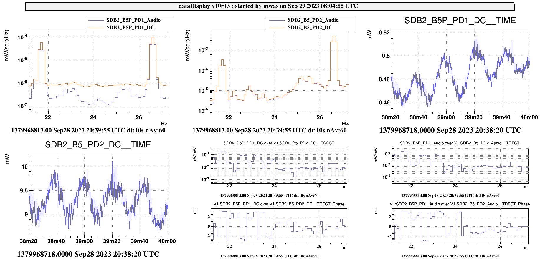
Figure 3, looking at earlier in CARM NULL 1F data is even more puzzling. Looking at the MICH and SRCL lines shows that the DC and Audio channel of each photodiode agree with each other, so there is no large issue with the relative calibration of the Audio and DC channels (there might be a few percent discrepency on B5P). What is completely strange is the transfer function at the MICH and SRCL lines between B5 and B5P.
- For the SRCL line at 26.6Hz the ratio of amplitude is 0.02 and the line is in phase in both photodiodes. So both S and P polarization go up and down together, the SRCL effect is not polarized
- For the MICH line at 21.7Hz the ratio of amplitude is 0.16 and the lines have opposite signs (pi phase in the transfer function). So the effect of MICH is polarized, if it increases the amount of S-pol light it reduces the amount of P-pol light at the same time.
The line ratio looking at the Audio or DC channels is the same. So it is less likely to be just a cross talk effect from other photodiodes that would see the MICH and SRCL lines much more clearly.
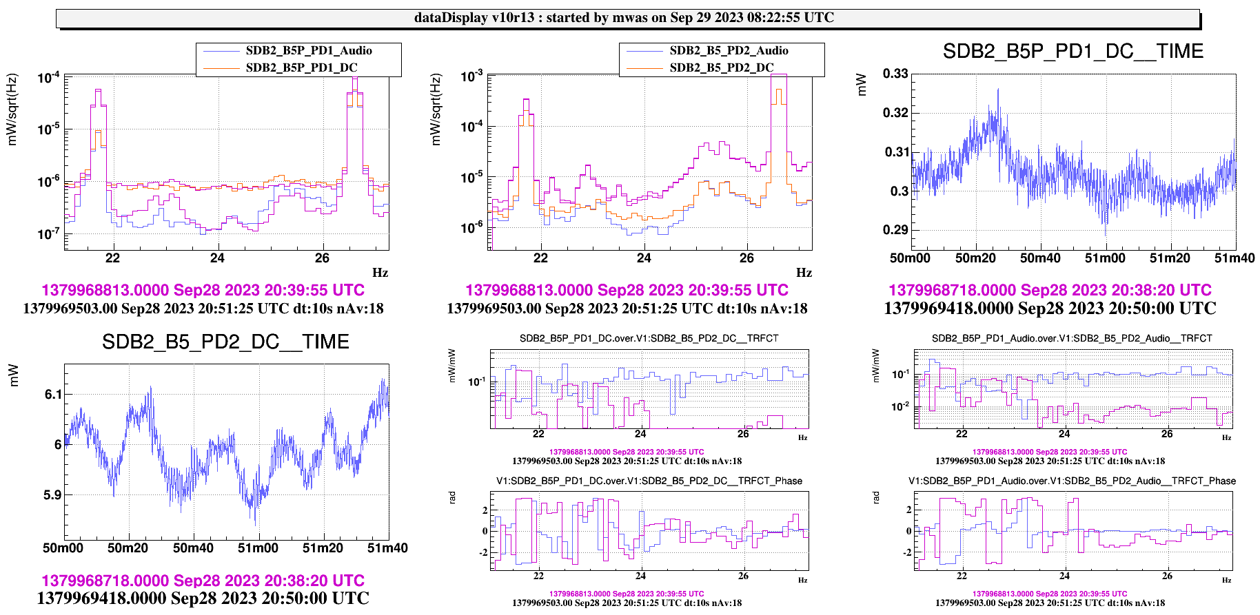
Figure 4 shows in purple the CARM NULL 1F data, and in blue/red data while the OMC is locking. The MICH and SRCL lines are smaller (not surprising, as I expect they are reduced at this stage), but the behavior of the lines in the B5 and B5p changes
- For the SRCL line at 26.6Hz the ratio of amplitude increased from 0.02 to 0.1 and stays in phase
- For the MICH line at 21.7Hz the ratio of amplitude decreased from 0.16 to 0.04, and stays opposite in phase between B5 and B5P.
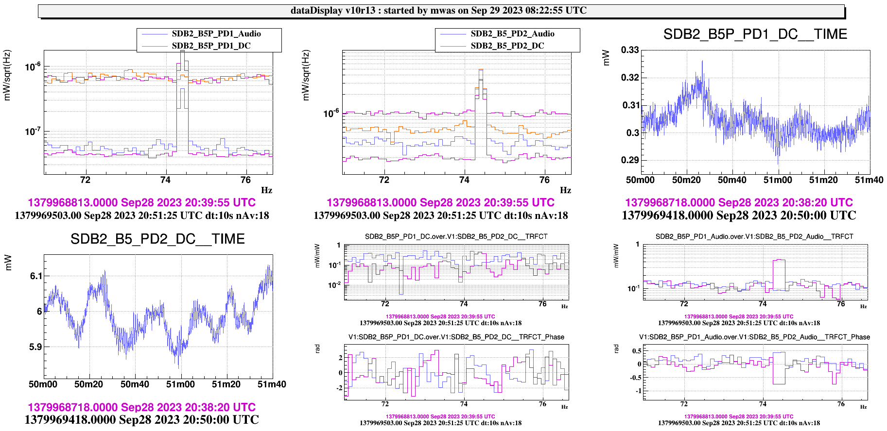
- For the DARM line at 74.4Hz (figure 5) the ratio of amplitude decreases from 0.45 to 0.09 and the phase changes from -0.8 to 0.4
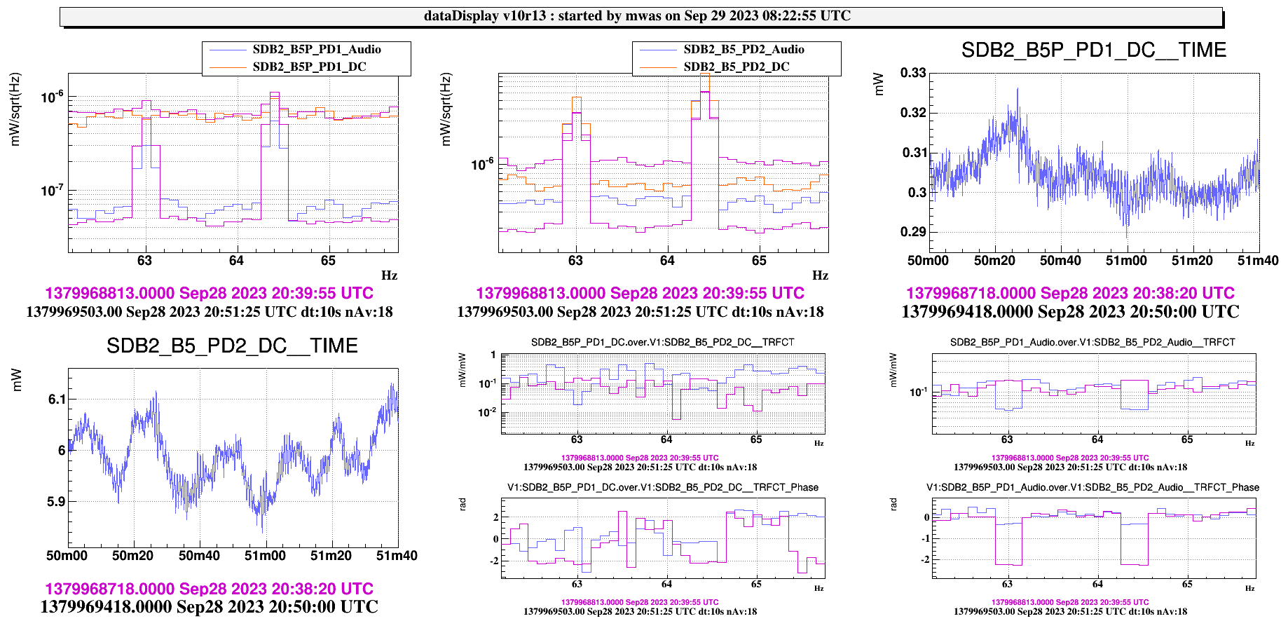
- For the PRCL line at 64.4Hz (figure 6) the ratio of amplitude decreases from 0.15 to 0.05 and the phase changes from -2.2 to -0.24
This is very puzzling, and worrisome that MICH changes the polarization of the light on B5.


