This afternoon we continued the recovery of the interferometer.
In the initial part of the shift we didn't manage, again, to go past the CARM_MC step as we were unlocking sistematically whenever we were approaching 40 mW of arms power after the CARM handoff. Later on, towards the end of the shift, we recoverd higher steps of the acquisition (up to CARM null 3f for few seconds).
-------
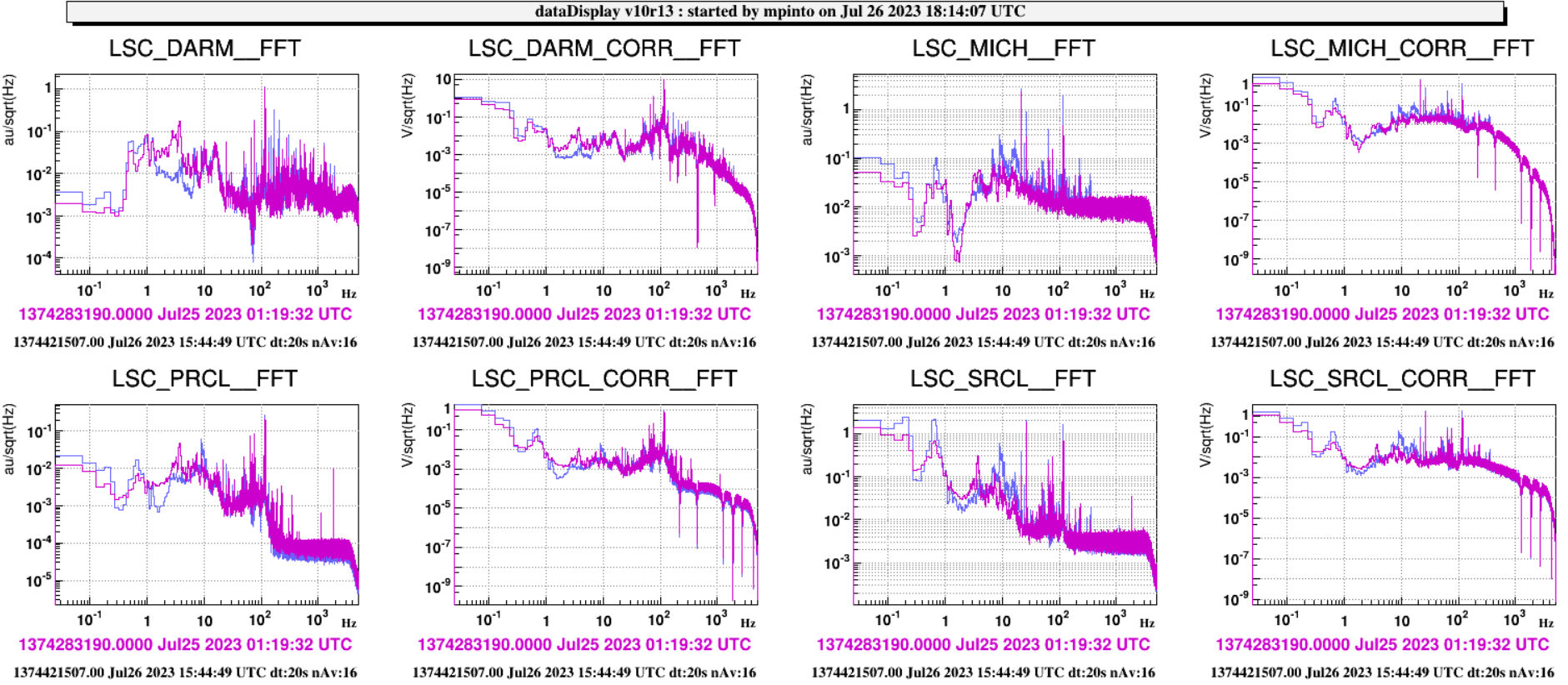
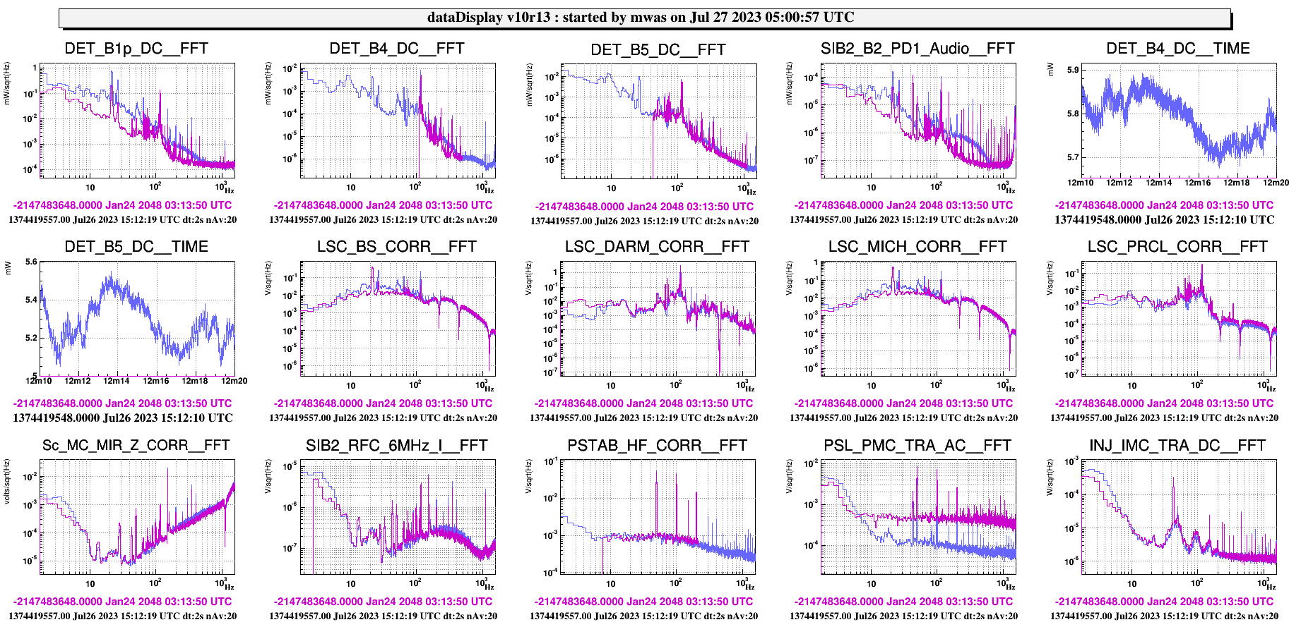
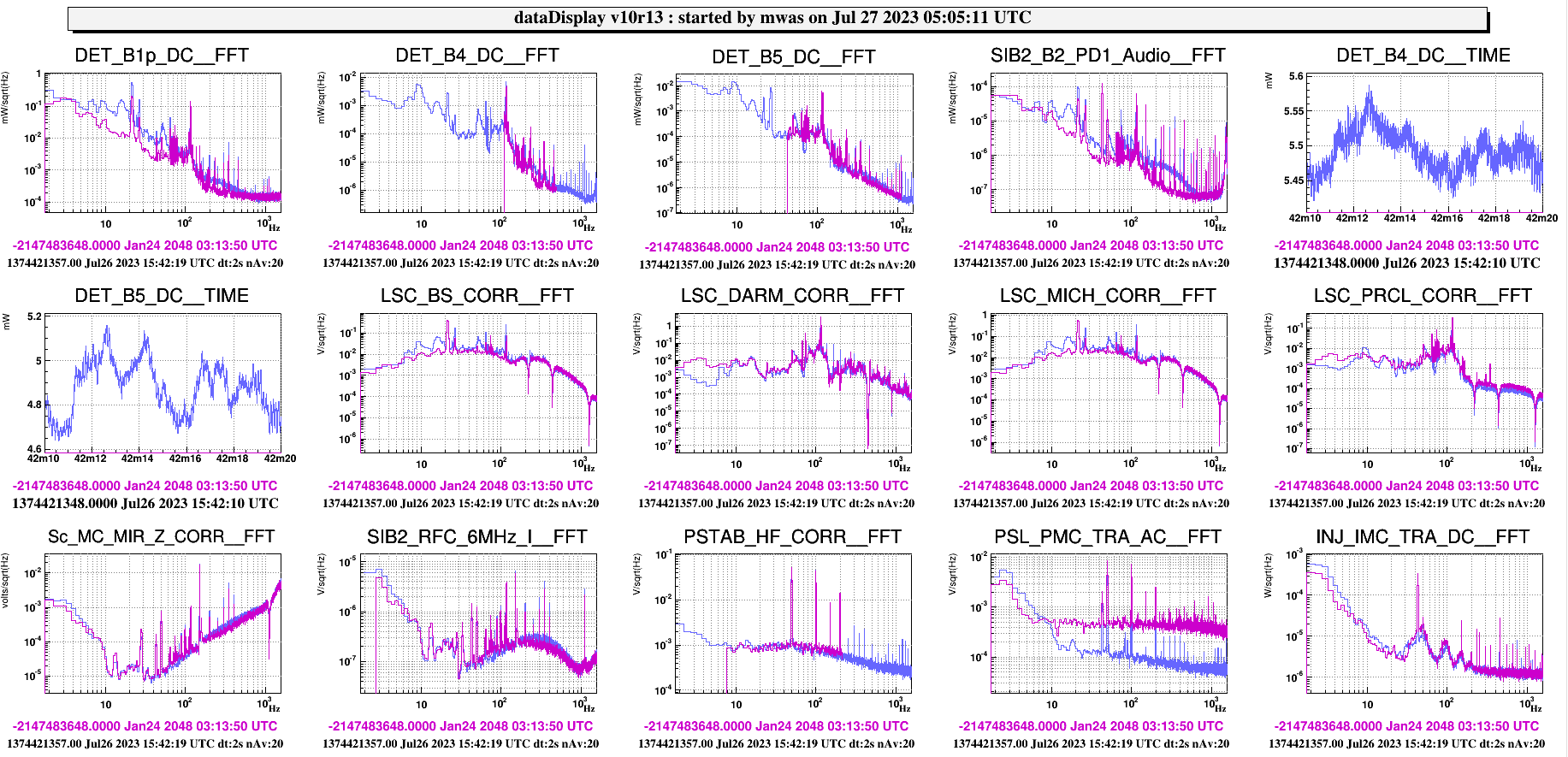
Michal noticed an excess of noise present at the DRMI 3f step (bump-like shape from 10 to 100 Hz), wrt to the working conditions pre-RAMS before its installation.
----------------------------------------
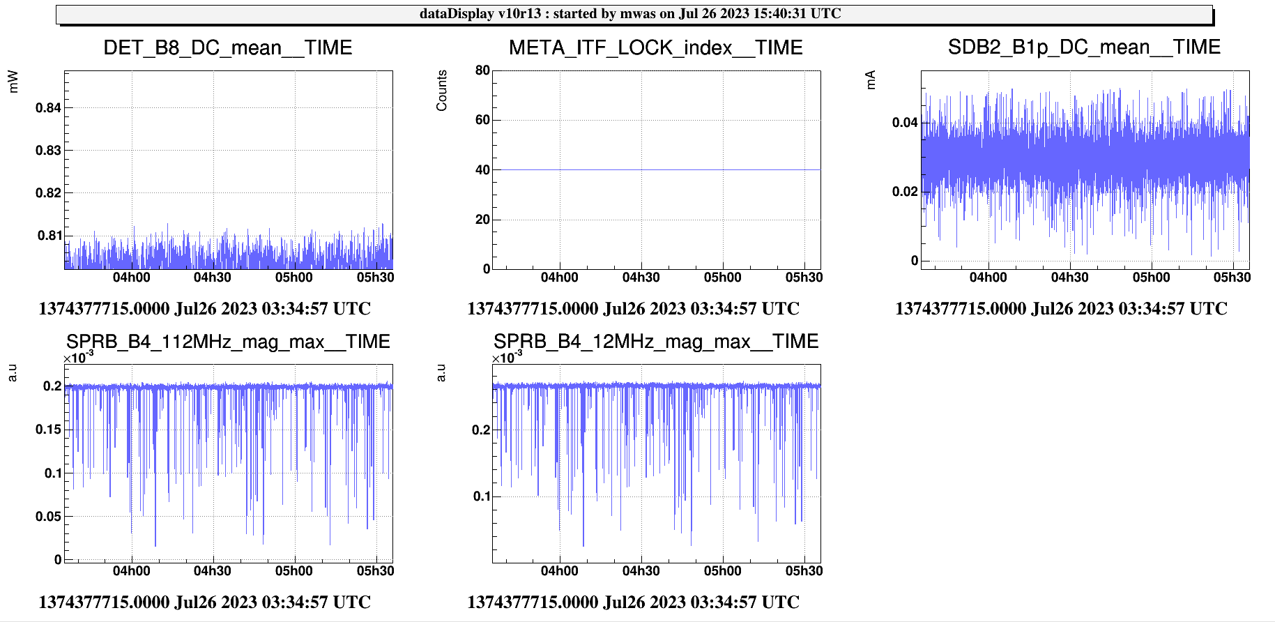
01.18 UTC jul 25: GPS during the night in which no bump was there.
----------------------------------------
We decided to open the loop, and see if there were visible differences.
15.30 UTC Gianmatteo went to the Lab to open the loop. At 15.32.29 UTC ALL has been switched OFF.
15.42 UTC we went back to DRMI 3f.
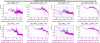
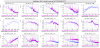
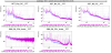
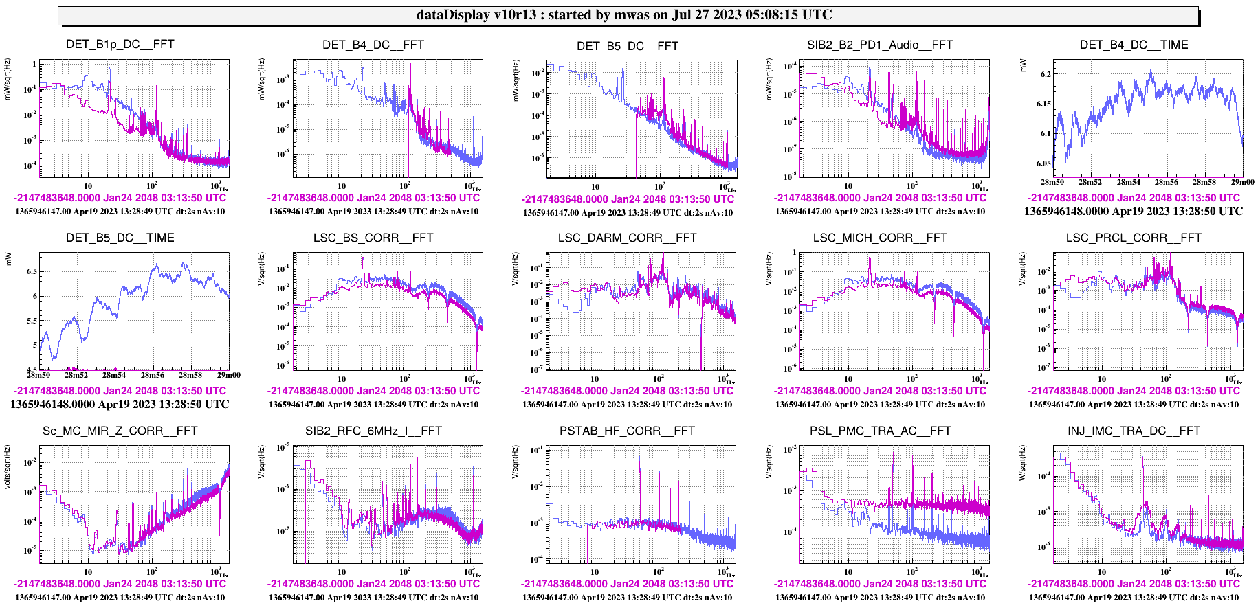
By opening the loop, we didn't notice any difference, as the bump at DRMI_3f stage was still present. So we continued the lock acquisition. In the attached picture, comparison of the Error signals and Correction signals spectra of the main DRMI and LSC signals is reported (purple: before RAMS; blue: After RAMS).
On the way to 40 mW of power we noticed that some parameter was a bit off-tuned, so in order to smoothly get past the ramp, we decided to go to 40 mW by hand, and try to adjust the loop gains step by step.
We put 10 mW of power for the ramp after CARM MC handoff (4.47 in MC_SET units).
We unlocked a couple of times due to 8 Hz oscillation (looks MICH gain too low).
So, we increased MICH gain up to an UGF of 20 Hz (up of a 30% = from 1800 to 2300 in the 1f/3f ratio).
While I was increasing by hand the CARM_MC_SET in order to reach 40 mW I injected also noise in order to measure the CARM_MC open loop. From the measurement, nothing unusual on the shape appeared. (MC_RFC Noise from 16.36 to 16.39 UTC)
MC SET increased with the following steps: 4.47 (10mW), 5.5 (15mW), 6.5 (20mW) and 7.5 (around 30 mW). ITF unlocked few seconds after reaching 30 mW at 16.39.54 UTC.
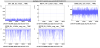
17.22 UTC We put the ITF in Single Bounc NI, in order to try to lock the OMC on the 56MHz and then on the 6 MHz to investigate if the RAMS servo is working as it's supposed to.
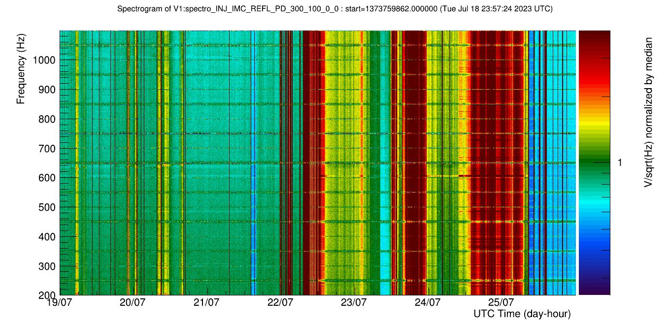
Once locked on the 56 MHz, we took a reference of the SDB2_B1_DC spectra, and then we switched on again the RAMS servo.
18.04 UTC RAMS servo back ON.
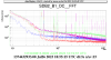
By looking at SDB2_B1_DC FFT, the effect of the RAMS (in terms of attenuation) is clearly visible.
Then, we locked the OMC on the 6MHz. In such condition, the effect of the RAMS while locked on the 6 MHz was not totally evident; at 18.30.25 UTC we increased the 8MHz mod depth from 0 to 6 dBm but no clear difference on the SDB2_B1 spectra appeared.
More details about the performed tests will follow.
.----
After dinner we kept going with the 'recovery'. We were able to go past CARM to MC step, but we unlocked at different steps of the acquisitions, e.g. 100 and 200 mW.
19.56.35 UTC unlocked at 200 mW (15-16 Hz oscillation)
a step 2 reduced PR TY TX gains and 169 MHz phases (of 0.3 rad) and reduced SRCL gain from 0.2 to 0.18
20.14.36 UTC unlocked at 100 mW (same 15-16 Hz oscillation)
at step 1 decreased SRCL gain from 0.25 to 0.22 and reduced of 0.3 rad the 169MHz phase
At the next attempt (20.28.41 UTC) we unlock on the way to CARM STEP 3 of 3 (400 mW) due to the same 15-16 oscillation. We tuned accordingly the parameters as for the steps before. (SRCL gain and 169 MHz phase)
----
20.46.14 UTC we unlocked on the way to CARM null 3f!
at that step we tuned the CARM B4 6MHz phase (reduced it of 60 deg accordingly to the delta applied yesterday on the other 6 MHz based signals).
--
at 21.04.50 UTC we recovered CARM null 3f. After 45 Seconds at 21.05.35 UTC we unlocked.
--
We left the ITF locked on the IR.

