- OMC scan: from 14:58UTC to 15:20UTC;

The IRIGB distribution cannot be switched off all the time as it is used to monitor the 100MHz clock distribution via the _timimg _error channel:
- it should be restored when the ITF unlock and disabled if needed at LOW_NOISE_2 or before
To re-enable the 100MHz clock distribution monitoring, the IRIGB has been switching ON for the 100MHz clock distribution:
- 2023-07-22-03h59m54-UTC info masserot Command '100MHz-IRIGB:irig on' executed
I have reused code from 6 months ago to analyze the OMC scan. This is based on counting the peaks and educated guesses on which mode is which, I haven't actually checked the camera image for each of them. /users/mwas/OMC/OMC_scan_demod_20230722/OMC_SCAN.m
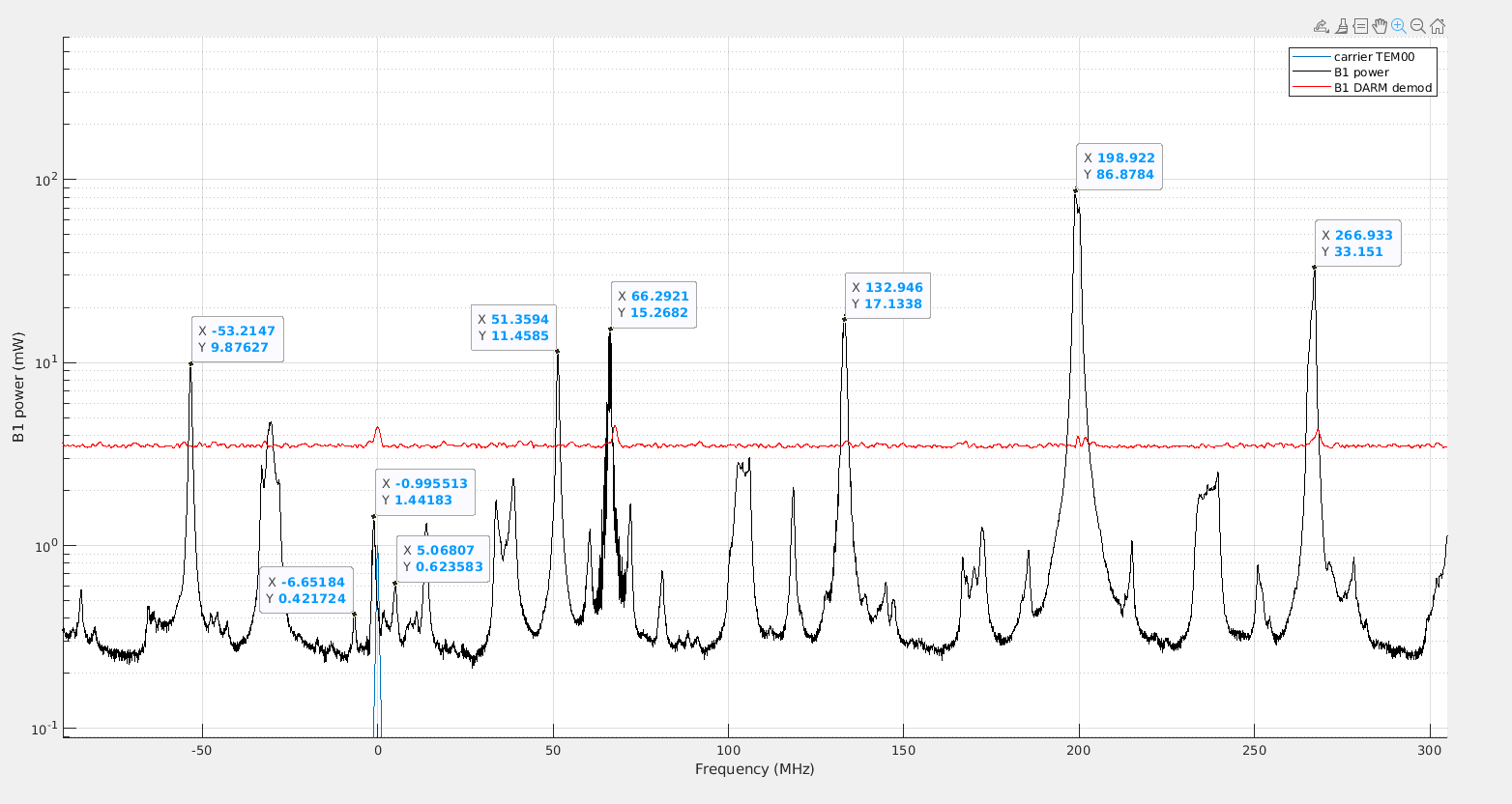
Figure 1 shows the result. The 56MHz sideband is rather well balanced, with a 15% difference. The 6MHz sideband is more misbalanced, with a 50% difference between LSB and USB, but more notably the order 1 mode has 3 times more power than the TEM00. This is reasonable, the 6MHz is close to the dark fringe, so TEM00 is cancelled and order 1 mode shows the imperfection in the destructive interference. It likely means that the BS alignment could be improved, at least from the 6MHz perspective. The B1p 12MHz demodulated at BS dither lines signal should be an easier to use figure of merit for the same issue.
What is also surprising is that the order 3 carrier mode is very high compared to the rest of the spectrum. Last scan I could find is from January. The order 3 mode was similar height as now, but all the other modes were also at the 50-70mW level. So the carrier HOM all improved with the exception of the order 3 mode that now stands out. I have no idea what that can mean.
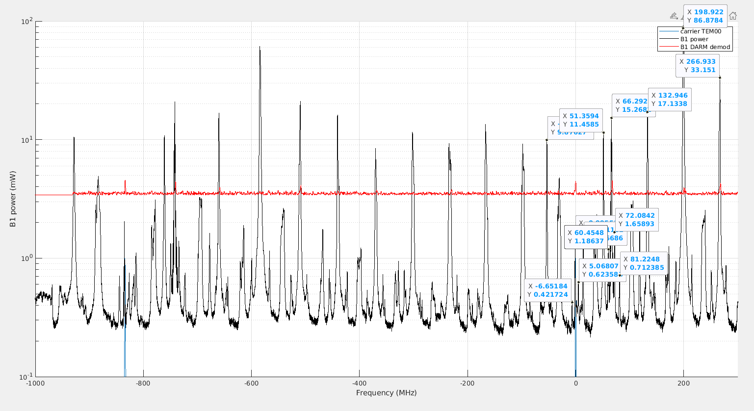
Figure 2 is the same data but showing a bit more than a full FSR (marked with the blue lines that point roughly to the carrier TEM00)
Below is the table of the measured peak height in mW in transmission of the OMC, I have also put them in the ITF parameter spreadsheet
| Carrier TEM00 | 1.4 |
| Carrier order 1 | 14.1 |
| Carrier order 2 | 16.1 |
| Carrier order 3 | 27.3 |
| Carrier order 4 | 1.2 |
| 6MHz USB | 0.42 |
| 6MHz LSB | 0.62 |
| 56MHz USB | 9.9 |
| 56MHz LSB | 11.5 |
| 56MH USB order 1 | 1.3 |
| 56MH USB order 2 | 0.7 |
| 6MHz USB order 1 | 1.2 |
| 6MHz LSB order 1 | 1.65 |
