At the beginning of the shift, we started by adjusting the alignment of the B1p and B5 quadrants on SDB2. We adjusted the beam centering on the QPD with picomotors, so that the galvo corrections were reduced.
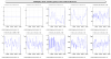
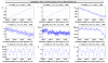
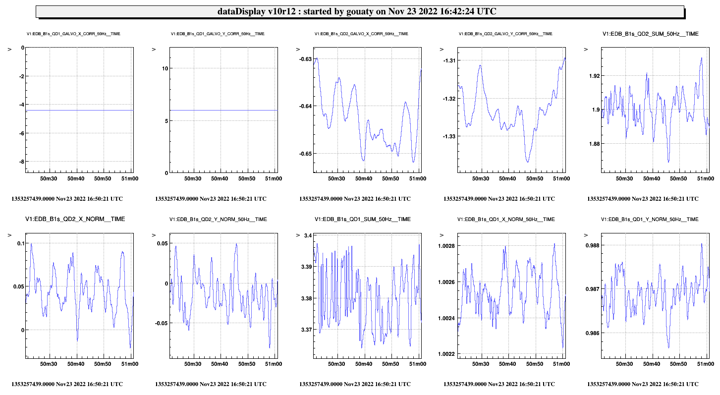
We also checked the centering of the EDB B1s galvos (see Fig.1). The B1s_QD2 quadrant seems to be aligned with galvos loop working, thus we decided to not modiffy this alignment (an alignment check on EDB is foreseen next week).
We then wanted to measure the spectrum of the OMC transmitted beam (when OMC locked on carrier TEM00) as a function of the transmitted power, with reduced side bands.
To this purpose Julia went to the central building to reduce manually the 82 MHz side band.
We put at 0 the modulation depth of the other side bands at ~16h55 utc:
cm_send('Lnfs100', 'SETAMPL', 0)
cm_send('Lnfs100', 'SET56AMPL', 0)
Note that the 8 MHz was already found at 0.
First we increased the fast trigger threshold on B1_PD1/2_DC to 50 mW in order to be able to use these photodiodes without triggering the shutter. SDB2_Photodiodes reloaded at 17h00m27 UTC.
In DET_MAIN.ini file, we increased the threshold on max_power_B1 from 30 to 100, in order to avoid triggering the safety.
Noticing that the B1s camera is spoiled by interferences, we asked the operator to move the PR mirrow away from its parking position by -30 urad in TY. This allows the get rid of the interferences.
OMC locked at 17h08m20 utc: 0.105 mW on B1_PD3.
Detuned polarization by acting on the waveplate channel 2 axis 2: +5200 steps > The power on B1 dropped below 90 mW. Opening B1_PD1/2 shutters > lead to PD overflow.
We then increased the current limit in SDB2_dbox_bench from 32 to 40 for both B1_PD1 and B1_PD2: config reloaded at 17h19m05 UTC.
We also restarted by mistake the SDB1_dbox_bench process, although it was not needed:
- 2022-11-23 17h25m52 UTC gouaty process:SDB2_dbox_bench stopped
- 2022-11-23 17h25m56 UTC gouaty process:SDB2_dbox_bench started
Increased again the current limit in SDB2_dbox_bench from 32 to 45 : config reloaded at 17h37m25 UTC
Detuned further the polarization by acting on the waveplate channel 2 axis 2 with another 1000 steps (total since the beginning +6200 steps) at 17h43m16 UTC
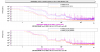
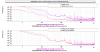
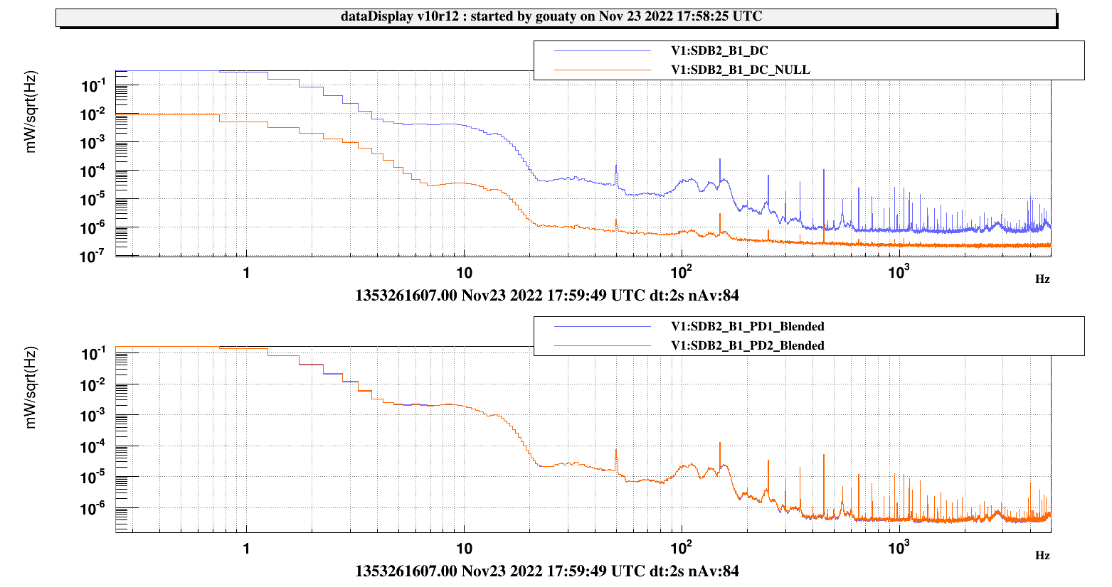
OMC locked with B1_PD1/2 opened at 17h53m40 utc, 50 mW per photodiode. Taking data until 18h03m40 utc. Fig.2 shows the spectrum of B1_DC and the spectrum of the NULL stream (measurement of shot noise) during this data taking. We can see that there is an excess noise with respect to shot noise even at high frequency.
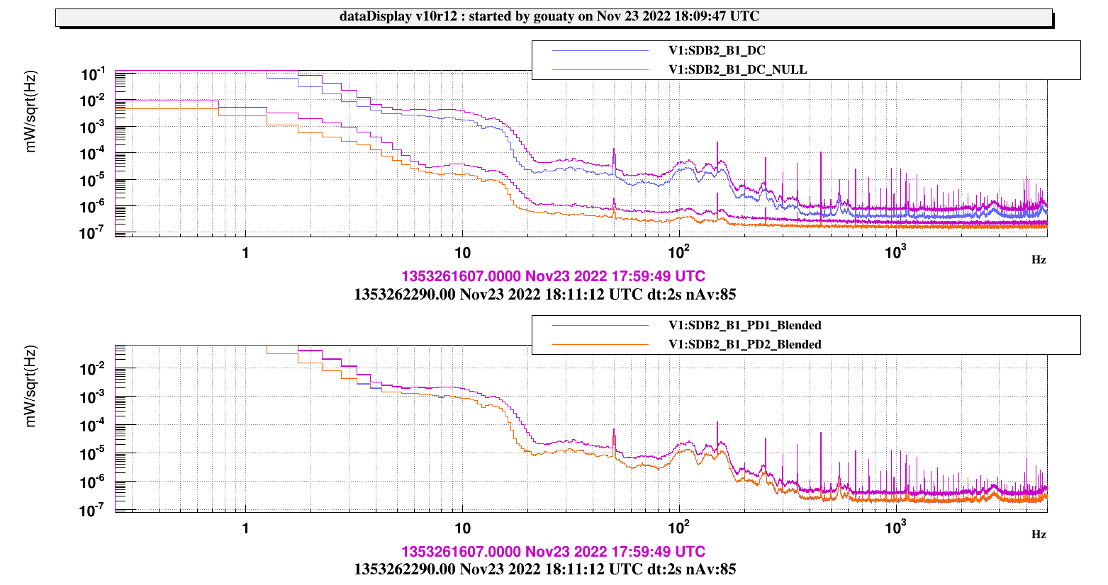
Mistuned further the polarization with waveplate channel 2 axis 2: +5700 (total since the beginning +11900 steps) > power on each photodiode B1_PD1/2 = 25 mW.
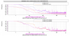
Taking data from 18h09m00 utc for 8 min. On Fig.3 we added the spectrum obtained during this data taking on top of the previous spectra. The extra noise seems to scale proportionnally to the B1 power while the shot noise scales as the square root of the power. We note that the noise below 20 Hz looks like a scattered light arch.
Undo part of the steps with the waveplate: -2000 steps
Scaning SDB2_LC: (nominal position TY = 950, TX = -280)
Adjust B1_M4_H picomotor by -900 steps to better center B1_PD3.
Adjust B1_M1_H picomotor by -800 steps to have the B1 camera centered.
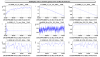
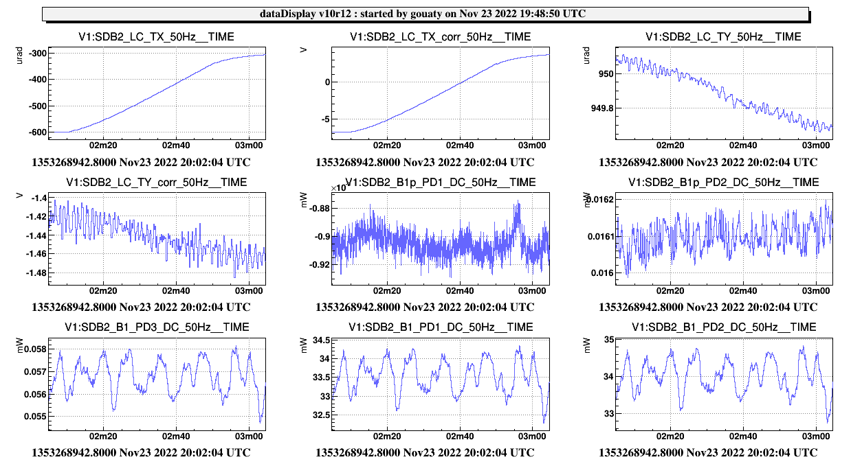
SDB2 TY scan after these adjustment shown in Fig.4. The three B1 photodiodes are well centered.
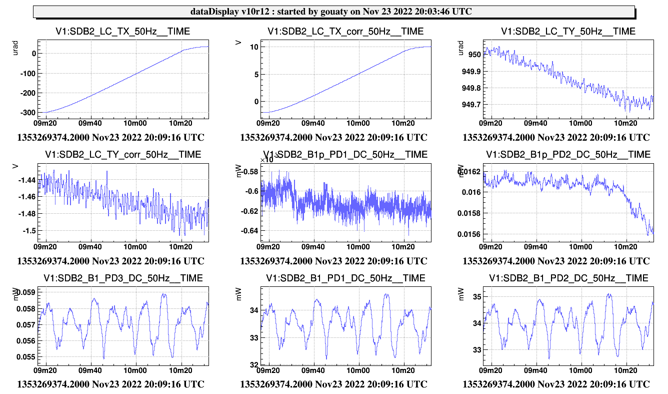
Scanned TX from -700 to 100 urad. We performed this scan in 2 steps (we had to rebalance the bench with picomotors in order to avoid saturation of the local control during the scan). See Fig.5 and Fig.6. During the scan the power remains constant on the three photodiodes.
Waveplate moved by +1800 > 25 mW on B1_PD1/2. Collecting data from 20h18m20 utc to 20h24m20 utc.
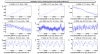
PR put back in parking position at 20h25m50 utc. The arch of scattered light noise at low frequency disappears (or is much reduced) when PR is properly parked. The B1 noise spectrum with PR out of parking position and in parking position are compared on Fig.7. Taking data in these conditions for 6 min.
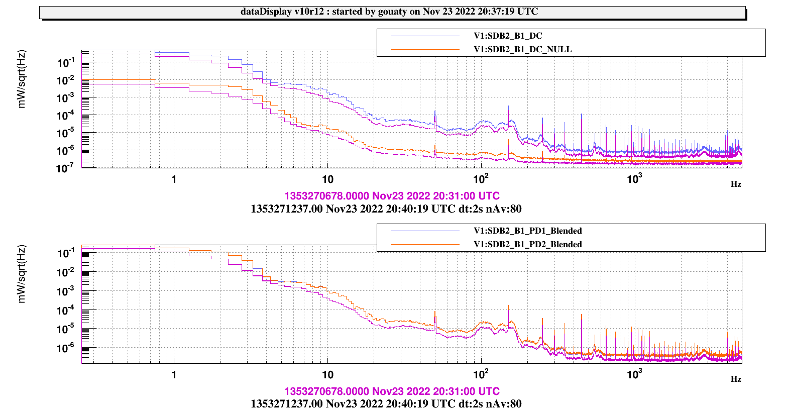
Waveplate moved by -5200 > 50 mW on B1 PD1/2. Taking data from 20h36m00 utc to 20h42m00. Fig.8 compares the B1 noise spectrum with 50 mW and 25 mW. Same conclusion as earlier concerning the dependency of the noise with the power.
PR moved again away from parking position by 30 urad at 20h47 utc. The apparition of the scattered light arch is clear on Fig.9.
Starting from 21h03m07 UTC we moved the waveplate by -7500 steps. Then we unlocked the OMC and scanned it around the P polarization peak in order to finely tune the polarization matching (doing little steps of ~100 steps between each scan).
We concluded the polarization matching tuning at 21h51m20 utc. In the last scan over the P polarization peak, the peak is not seen anymore neither on B1_PD3 or on B1_PD1/PD2, which indicates a good tuning.
Performing a decreasing scan at the end of the shift (after 22h00 utc):
order 0 : 135 mW (0.108 mW read on B1_PD3 see below)
order 1: 2.3 mW (total 2 PD) > 1.7% of misalignment
order 2: 1.8 mW (total 2 PD) > 1.3% of mode mismatch
Comparing B1_PD3 and the other photodiodes after the polarization tuning shows that 0.08 mW on B1_PD3 corresponds to 50 mW on each B1_PD1/2 (thus 100 mW in total on B1). Thus the power reached when OMC is locked on PD1+PD2 is 0.108/0.080 * 100 = 135 mW. This is in a good agreement with the cavity having 10% of losses, and the total power reaching the bench being around 150 mW.
PR put back in parking position at 22h00 utc.
Modulation depth of 56 MHz and 6 MHz restored at 22h29 utc
cm_send('Lnfs100', 'SETAMPL', 12)
cm_send('Lnfs100', 'SET56AMPL', 12)
Restored max power in DET_MAIN: max_power_B1 = 30 at 22h32 utc.
Restored power threshold on B1_PD1 and PD2 at 25 mW, SDB2_Photodiodes configuration reloaded at 22h33m50
Restored current limit on B1_PD1/PD2 photodiodes in SDB2_dbox_bench. Configuration reloaded at 22h39m53 UTC .
Closing OMC shutter at the end of the activity.
A few findings things to keep in mind:
- The current PR parking position is not good for the OMC, as it produces interferences fringes on the B1s beam (and maybe can impact B1 also). The B1p camera image is not affected because the ghost beam is better separated, however we notice that there is an excess power on the B1p photodiode associated to the ghost beam.
- When the PR mirror is moved away from its parking position, this induces scattered light noise.
- The calibration of B1_PD3 has changed. The ratio B1 power / B1_PD3 is now equal to ~1250. Can this be an indication that the polarization eigenstate of the OMC is different from the previous OMC ? We already know that the transmission of the beam splitter in front of the B1_PD3 photodiodes is very different for the two polarization. The transmission in P polarization is about 10 times bigger.

