Reports 1-1 of 1 Clear search Modify search
AdV-INJ (Electro optical modulation system (EOM))
derossi, chiummo, spinicelli, gosselin - 22:50 Friday 18 November 2022 (57822) Print this report
INJ recovery after the EOM installation - work in progress

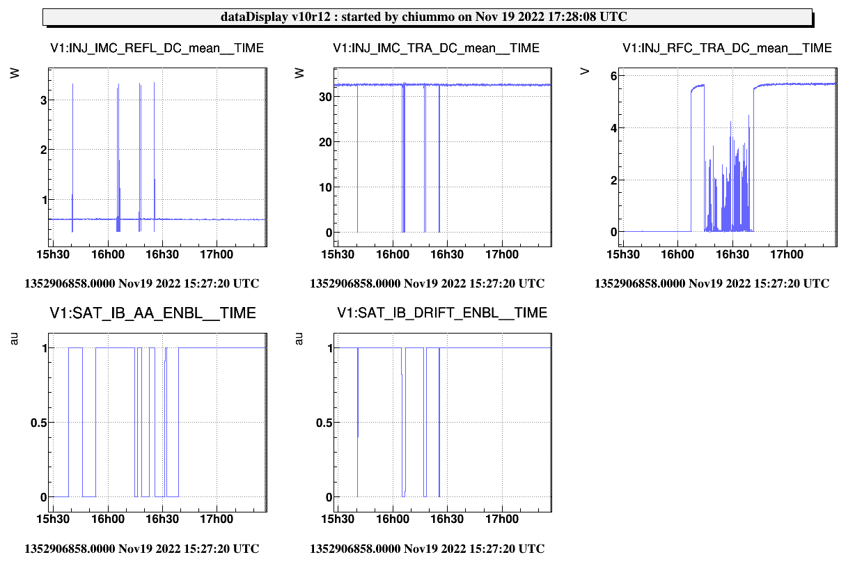
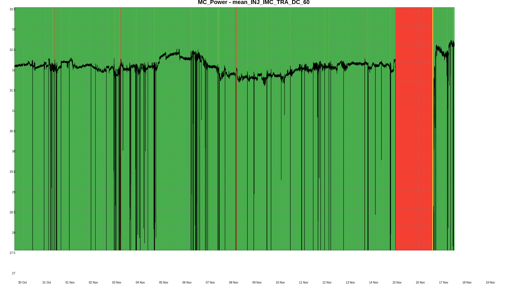
This afternoon we carried on the recovery of the injection system.

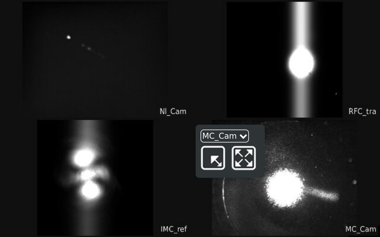
We could relock the IMC but it was very difficult to find a good alignment because of the appearence of high order modes. We had to displace the beam horizontally on the end mirror to get away from these resonances.

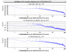
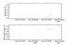
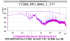
In this new "good" position some loop oscillations at 187kHz occured and they were killed by further attenuation of the IMC error signal by 4 dB. We do not know the cause but one check we could do is to better tune the 22 MHz demodulation phase.

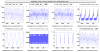
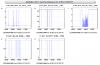
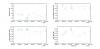
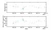
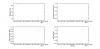
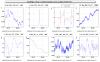
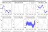
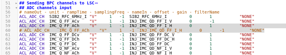
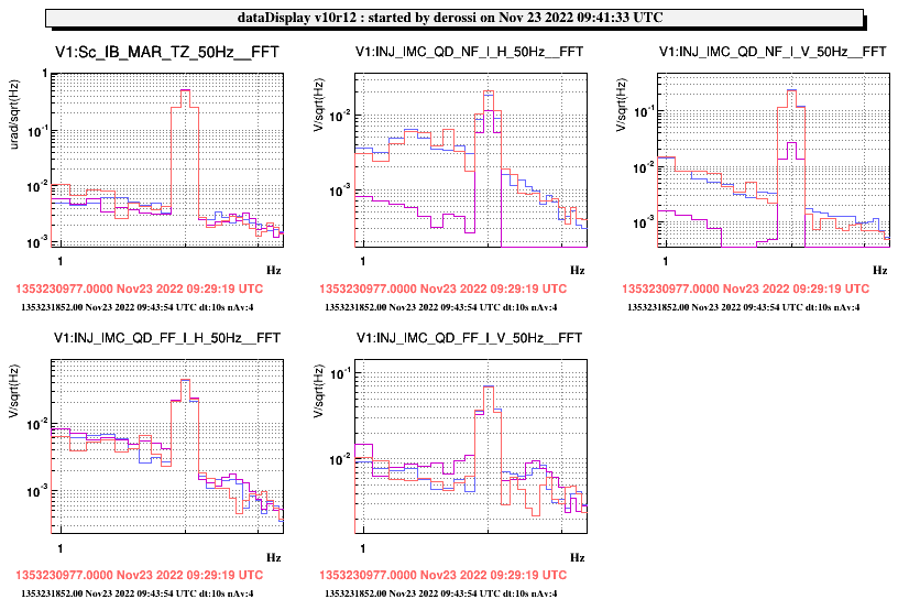
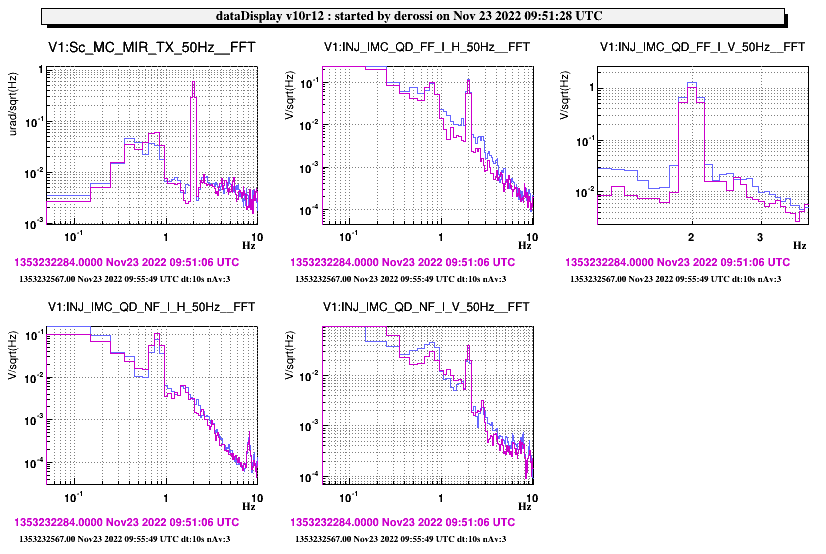
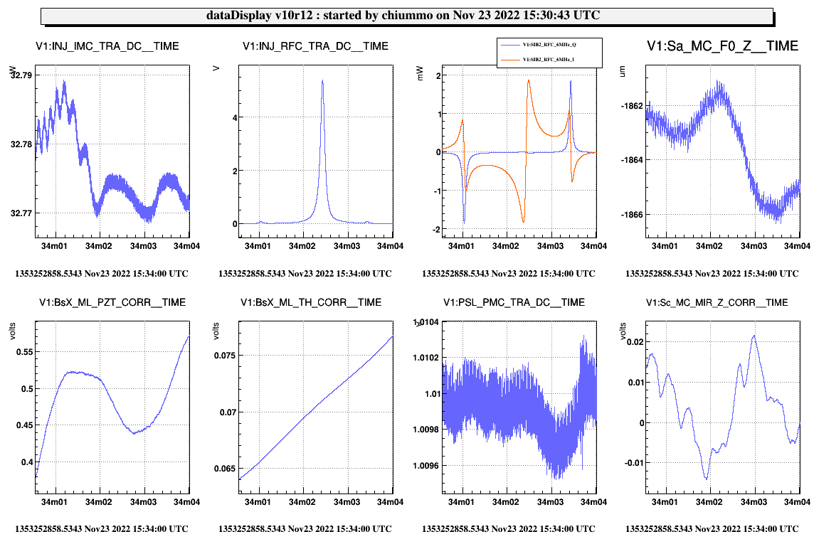
Once this oscillation was killed, we measured the new automatic alignment sensing matrix. However, as soon as we closed the alignment in drift control, the BsX X CORR (which are closed on IMC QD FF I H) drifted away. We should also check the demodulation phase of the quadrants for the automatic alignment (in particular FF).


Injection time
MC ty gps = 1352835395.00
IB ty gps = 1352835057.00
MC tx gps = 1352835302.00
IB tx gps = 1352834886.00
IB tz gps = 1352835177.00

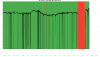
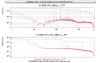
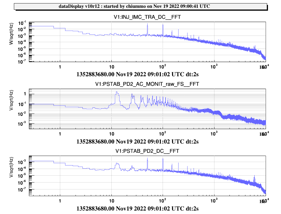
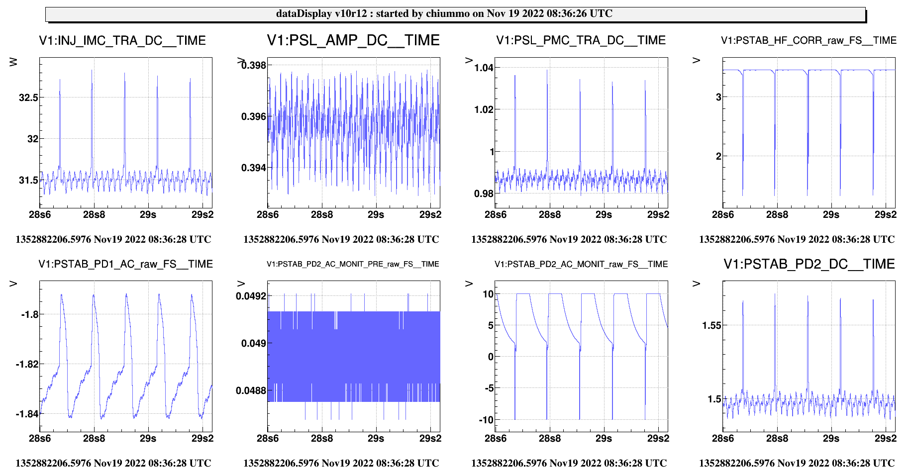
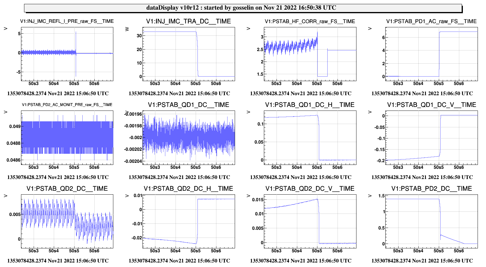
We also encoutered problems in closing the PSTAB loop, but this is probably induced by an oscillation on the IMC itself (to be confirmed).


Comments to this report:
chiummo - 18:32 Saturday 19 November 2022 (57827) Print this report

Continued the recovery of the Injection after the work on the optical components and on the control electronics for the new EOM and the new PSTAB.

Found IMC locked, alignment close to what we left yesterday (kudos to suspensions)

  • The noise on IMC_TRA_seems to be a high 50Hz, while PSTAB_PD2_AC shows 15Hz and many harmonics. Anyway, the PSTAB loop cannot be engaged in these conditions, needs to be investigated.

  • Our colleagues of the EGO Electronics Group warned us that while installing the hardware for the 81MHz in the Piscina, they found a loose knob on the phase shifter for the 22MHz (rack closer to laser lab). They have fixed it but told us that probably we had to retune the phase for the IMC loops. I have turned the knob of phase shifter in the piscina - output 3. Saw that changing the phase I caused a loop oscillation in the IMC freq, so I increased the attenuation of the error signal input to the rampeauto to kill the oscillation.

    • New parameters: potentiometer of phase shifter output 3 is at 6.50 (was 3.0); attenuation is 13dB (was 6dB).

  • Pstab still plagued by low frequency lines and it is impossible to us. Will postpone the diagnostic after the work by Artemis team on the PSTAB

  • Yesterday we did not manage to implement the AA on IMC, so today a new injection was performed on the mirror/bench (report attached) after being sure that the alignment of the IMC was compatible with small offsets coming from demodulated RF quadrants.The sensins matrix calculation takes into account the sign of the RF quadrants, but for the BsX_X loop which lives in the DSP. For the latter, a flip of sign was needed after the tuning of the 22MHz phase. This was implemented in ISYS_ACL (see screenshot) for the INJ_IMC_QD_FF_I_H channel.

    • Test with FF_I_H flipped sign in ISYS_ACL (line 59: was -1 -> +1)

    • Drift control works, not optimal, but survived several lock acquisitions

      • Tried to reduce the gain on vertical tilt sensing, but when switching in full bandwidth it breaks the lock

      • RFC locked without problems

Several attempts have been also made to engage the full bandwidth  AA, but an oscillation on vertical tilts regularly breaks the lock, to be further tuned.

Overall, INJ subsystem has been restored to minimal functionality. We need to engage full bandwith in AA, and PSTAB loops. The completion of the recovery (and the full characterization) will be performed after the work on PSL scheduled in the next days.

Images attached to this comment
Non-image files attached to this comment
chiummo - 9:46 Sunday 20 November 2022 (57828) Print this report

EIB loop was ringing this morning, cured by disabling and then enabling the PID on the VPM.

From GPS 1352967980 to GPS 1352968700 clean scan of the RFC. Data will be analyzed offline.

melo - 16:52 Monday 21 November 2022 (57835) Print this report

I have analyzed the INJ throughput losses before and after the EOM installation.

The analysis before the installation is the following (1st to 16th of November):

In Fig. 1 we can see that the mismatch (left upper graph) was oscillating around 8%, while the throughput losses (right upper graph) of the IMC cavity were arounf 16%.

In Fig. 2 it is shown in the bottom graph the PSL to ITF throughput, which were around 65% (i.e., the ratio between the calculated power at the output of the PMC (we have estimated 7% losses from the output of the PMC to the output of EIB) and the power at the input of the interferometer (which is estimated to be 7.5% less w.r.t the output of the IMC due to SIB1 losses)).

After the EOM installation we have (from Nov 19th to 21st):

Fig. 3 shows that the mismatch improved a little bit, to 7.4%, and the throughput losses dropped to 11.3% after Nov 20th.

In Fig. 4 we can see that the PSL to ITF throughput increased and it is now around 69.5%.


As a conclusion we can say that the mismatch and the IMC cavity losses improved by 0.6% and 4.7%, respectively. Also the PSL to ITF throughput has improved roughly by 4.5%.

Images attached to this comment
chaibi, coulon, derossi, chiummo, gosselin, spinicelli - 10:10 Tuesday 22 November 2022 (57844) Print this report
Yesterday, the Pstab issue was investigated:

- The AC signals had unusual behavior. Therefore, a diagnosis box were plugged directly to the flange on the injection tower. The current provided by the power supply was 2x150mA. The Pstab PDs provided correct signals (AC and DC with no beam since the IMC lock requires a Pstab DC signal) except for one AC signal which was much smaller than expected.

- In the EEroom, the signals had unusual behavior which prevented the lock of the Pstab. In particular, the AC signals had an offset of 2V.

- The power supply next to the patch panel, was at ±4V instead of ±15V because it was unable to provide enough current(limited to 2x200mA). This was confirmed by testing another power supply. When the IMC is unlocked, the current was around 2x 220mA which is higher than the one measured directly on the flange ; this remains not understood. But, the status of the power supply was fluctuating. Thinking that this is related to the intermittent resonance of the IMC, blocked the beam on the laser bench. The power supply current became stable. This was also checked on the flange of the injection tower.

- The IPC of Pstab was adjusted to reduce by a factor of 2 the power injected into Pstab optic box. The current provided by the power supply was below 300mA. PD_DC was then at 0.8V which allowed to recover the Pstab.

- The limit of the power supply output current was slightly increased (350mA) which allowed to increase the laser power to almost reach the initial value (this corresponded to an output current of 304mA an 331mA). During the last increase of the Pstab laser power, the PD2_DC suddenly vanished and it was no more possible to lock the IMC. We tried to find a new position of the corresponding IPC without any success. The power supply current dropped to 214mA and 231mA.

- We switched then to PD1_DC (on the patch panel, no channel was assigned) and some IMC resonances were observed but not enough to lock the IMC. Then, the IMC rampauto was modified so to accept the INJ_IMC_TRA signal as a trigger, which allowed to lock the IMC. The Pstab IPC was then adjusted so to obtain 0.3V on PD1_DC. The next step will be to check the status of the Pstab photodiodes on the flange on the IMC tower.

To be continued.
gosselin - 10:44 Tuesday 22 November 2022 (57845) Print this report

On the bottom right-hand corner of the figure attached, one can see the unsual behavior of the photodiode read by the channel PSTAB_PD2_DC (linear decrease between 50s5 and 50s6). After this moment this photodiode stop working.

Images attached to this comment
derossi, chiummo, melo, ruggi - 12:24 Wednesday 23 November 2022 (57867) Print this report

This morning we checked the tuning of the RF quadrants for the IMC automatic alignment.

We followed the same procedure as reported in eLog #44643

- IMC NF quadrant tuning --> maximizing the 2 Hz line injected on IB MAR TZ (plot 1)

- IMC FF quadrant tuning --> maximizing the 2 Hz line injected on MC TX (plot 2, the red is the old value)

The phases were already quite good we only did a fine tuning.  We measured the sensing matrix :

PR_SUM_CH MC_ty 19.70 MCT_h_err 0.00 FF_ACh_err 0.00 NF_ACh_err

PR_SUM_CH IB_ty 34.50 MCT_h_err 0.00 FF_ACh_err 1.08 NF_ACh_err

PR_SUM_CH MC_tx 12.11 MCT_v_err -0.58 FF_ACv_err 0.17 NF_ACv_err

PR_SUM_CH IB_tx 42.76 MCT_v_err -0.48 FF_ACv_err 0.14 NF_ACv_err

PR_SUM_CH IB_tz 10.59 MCT_v_err -0.18 FF_ACv_err -0.82 NF_ACv_err

Injection time (duration = 120 s)

MC ty gps = 1353235522.00

IB ty gps = 1353235035.00

MC tx gps = 1353235378.00

IB tx gps = 1353234869.00

IB tz gps = 1353235207.00

We finally closed the alignment in full bandwidth (plot 3, blue in full and pink is drift control)


Images attached to this comment
chiummo, De Rossi, Gosselin, Melo - 16:58 Wednesday 23 November 2022 (57875) Print this report

RFC PDH was found heavily mistuned (first plot: in-phase and quadrature error signal have the same amplitude), and this yelded some extra frequency noise at low/intermediate frequency (second plot).

We tuned the SIB2_RFC demodulation phase while scanning the RFC via the MC F0 z position as usual (third plot), via python console:

/users/optics/ISC_scripts

In [8]: run LSC_init.py

 SIB2.RFC_6MHz_phi0.AcParamGet()
cm_send('SIB2_Photodiodes', 'AcParamGet', 'RFC_6MHz_phi0')
Received AcParam message from SIB2_Photodiodes

# nameOut - unit - rampTime(s) - sampling frequency(Hz) - value - flag
ACL_CONST_CH RFC_6MHz_phi0   "rad" 0 10000 3.46 0

 SIB2.RFC_6MHz_phi0 = 3.46 - 2*pi /6
cm_send('SIB2_Photodiodes', 'AcConstChSet', 'RFC_6MHz_phi0', 2.4128024488034026)

and then saved the phase to ACL (line 147) of https://vpm.virgo.infn.it:40000/editor.html?editable=SIB2_Photodiodes

The result is shown in plot 4. Not that big a reduction of noise, just some slight improvement of RMS.


Images attached to this comment
bersanetti - 17:21 Wednesday 23 November 2022 (57876) Print this report

I updated the value in the configuration file of the INJ Automation, and corrected a typo in the Acl configuration file (swap of value/ramptime).

The value has also been updated online, as it was still 3.46 (the old one).

chiummo, Bersanetti - 10:56 Thursday 24 November 2022 (57886) Print this report

Indeed, after Diego made the tuning happen in the real world (thank you!), some effect on the RFC loop is visible (see first plot). Now it is like it was before the intervention on INJ.

Images attached to this comment
mantovani, chiummo - 10:20 Tuesday 13 December 2022 (58093) Print this report

The modulation index of the 56MHz in this scan (20th of November) is ~ 0.12

Images attached to this comment
Search Help
×

Warning

Error

The present report has been modified outside this window. Please check for its integrity in the main page.

Refreshing this page will move this report into drafts.

×