All the six AA automatic alignment were running (DIFFp, COMMp, PR, SR, BS, IB).
The configuration was the 'standard one' for DIFFp, PR, BS, IB.
In addition:
- COMMp was locked on B4_QD2_6MHz
- SR was locked on the double demodulation of the SR angular dithering lines from B1p_56MHz
In addition the two input mirrors pointing is locked on the average beam center on the cavity mirrors.
So, I believe that this is the first time that we have all the 6 alignment degrees of freedom of the ITF locked together with two pointing's.
The only remaining degree of freedom is the starting point of the beam at the input of the interferometer (the third point to fix the ITF plane) that we do not control (yet).
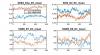
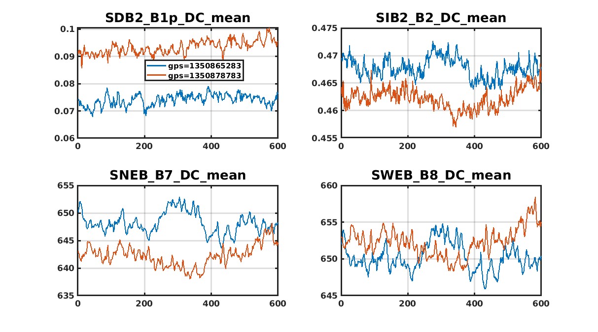
After the thermal transient, the beams positions were quite stable on the cavity mirrors (Figure 1, bottom center plots).
During the lock one can observe a linear increase of the B1p DC from 0.075 to 0.1, so relatively low but increasing (see top-left plot in Figure 1).
At the same time the power in arm cavities started at the same level (650 mW) but then the power increased in the North cavity (to 655 mW) and decreased in the West (to 640 mW).
So, these are good values but do present interesting drifts that might be related to the increase of the dark fringe power.
I tried to see if I can find these drifts somewhere else.
There are two interesting facts:
1) There is small drift on the demodulation phase of the BS (see Figure 1, bottom right plot)
2) There is a linear drift on B4_QD2_H_56MHz_I (Figure 2, bottom right plot).
Regarding 1)
It would be interesting to have a slow servo keeping the demodulation phase at the right place.
Regarding 2)
This is a new observation which I have not seen before.
It might indicate that there is some drift in the alignment of BS or of the SR (which can also explain the drift of B1p_DC).
Maybe the implementation of the AA loops and the two pointing loops allows seeing some signals in the B4_QD_56MHz quadrant that we cannot see otherwise.
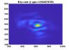
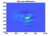
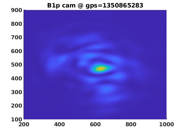
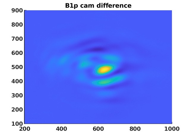
Here is a comparison of B1p image on the camera at two gps:
- 1350865283; 4000 s after the beginning of the lock, when the fringe was darker
- 1350878783; 17500 s after the beginning of the lock,when the fringe was brighter
The two images looks equal in shape, but different in amplitude. This is about what has been observed after a change of NE_RH power (NE ROC tuning).
In addition to the change of B1p, also a difference on B7 power was visible, and not on B8. Again, an explanation could be a change of north cavity matching.
