In the past few days, we did some efforts on the pointing loop with two PSDs, but it seems the loop cannot work as we expected. We may have some problems regarding the position of the two PSDs, but due to space limitations on the end bench, it will be difficult to further improve the situation.
So hereby we propose another possible strategy to control the injection direction of the green beam. We will use the dithering lines on the filter cavity mirrors, demodulated from the longitudinal correction signal, and feedback to the M5 and M7 mirrors. Our concern about this loop was that line injection will add noise to the lock. So what we propose is that we run this loop every day or a few days once to center the beam on the cavity mirrors and then use one actuator and one PSD loop to keep the beam at this position. In the past what we observed is that in the period of a few days the pointing loop with one PSD could keep the position of the beam, but in any case, we will test this stability again in the next days.
In order to implement the loop with the dithering lines, we first adjusted the demodulation phase of the dithering lines.
ACL_CONST_CH FCIM_DRIFT_TX_phi0 "rad" 0.0 LOOP_FREQ 1.5
ACL_CONST_CH FCIM_DRIFT_TY_phi0 "rad" 0.0 LOOP_FREQ 1.6
ACL_CONST_CH FCEM_DRIFT_TX_phi0 "rad" 0.0 LOOP_FREQ 1.75
ACL_CONST_CH FCEM_DRIFT_TY_phi0 "rad" 0.0 LOOP_FREQ 1.6
The amplitude of the lines we are using now is 0.25 for TX and 1 for TY. This could still be optimized to have less impact on the locking.
We measured the sensing matrix from M5 and M7 to the dither lines error signal and with the matrix to drive M7, we have a new 4*8 driving matrix. When we need to change the error signals used for the loop, we just need to change the coefficients in the matrix. Below is the one used when using the dither error signal:
ACL_MATRIX_BEGIN GR_BPC2_DRIVING 1 FCIM_DRIFT_TX_demod_I FCIM_DRIFT_TY_demod_I FCEM_DRIFT_TX_demod_I FCEM_DRIFT_TY_demod_I NF_PSD_X_NORM NF_PSD_Y_NORM FF_PSD_X_NORM FF_PSD_Y_NORM
ACL_MATRIX_CH GR_M5_BPC2_X "" -0.0001 0.0034 -0.0003 0.0023 0 0 0 0
ACL_MATRIX_CH GR_M5_BPC2_Y "" -0.0015 0.0003 0.0014 0.0001 0 0 0 0
ACL_MATRIX_CH GR_M7_BPC2_X "" -0.0001 -0.0014 -0.0003 0.0020 0 0 0 0
ACL_MATRIX_CH GR_M7_BPC2_Y "" -0.0004 0.0002 -0.0012 -0.0001 0 0 0 0
ACL_MATRIX_END GR_BPC2_DRIVING
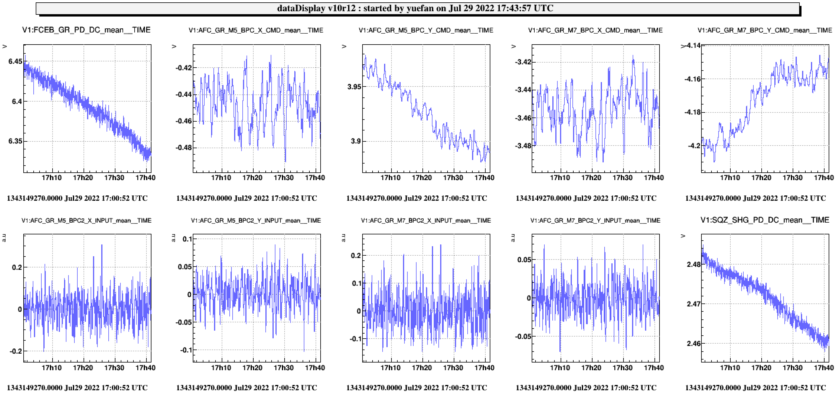
In the attached plot, the loop was closed for about 40min, the X direction shows almost no change, and in Y direction we could see about 0.05V of change, we still need to understand if this is the real correction of the beam direction of it is some drift caused by the loop. To be noted, the drift of the green transmitted power seems to be coming from the SHG power reduction.
Since yesterday the PSD has been moved, so we measured again the sensing matrix from M7 to FF PSD (the one we used in the past for the pointing loop). The sensing matrix is shown below
| M7 X | M7 Y | |
| PSD x | 0.0141 | 0 |
| PSD y | 0 | -0.0183 |
The pointing loop is closed with the dither line error signals to check the long-term performance.