IMC working point
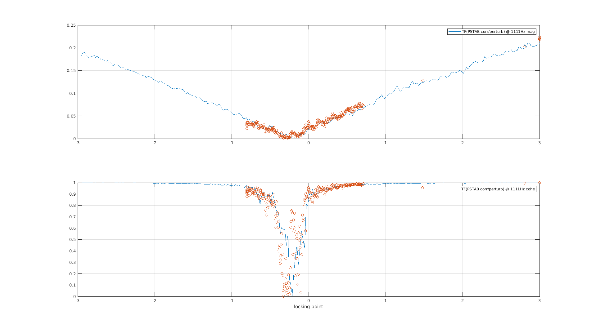
We started the shift by doing a check of the working point of the IMC by trying to minimize the coherence beween PSTAB_CORR and the perturbation injected in the IMC error signal.
The RFC was unlocked, we switched off the 6 8 and 56 sidebands and we set the amplitude of the 1111 Hz line to 0.2 on the vpm.
09:08:40 scan of +- 3 V on the fmoderr offset on vpm
09:42:10 scan of +-0.8 V
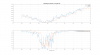
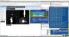
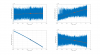
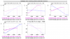
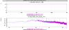
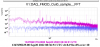
Figure 1 show the TF and the coherence of those two scans. The good working point seems to be -0.27 V. It waas previously set to -0.3 V
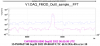
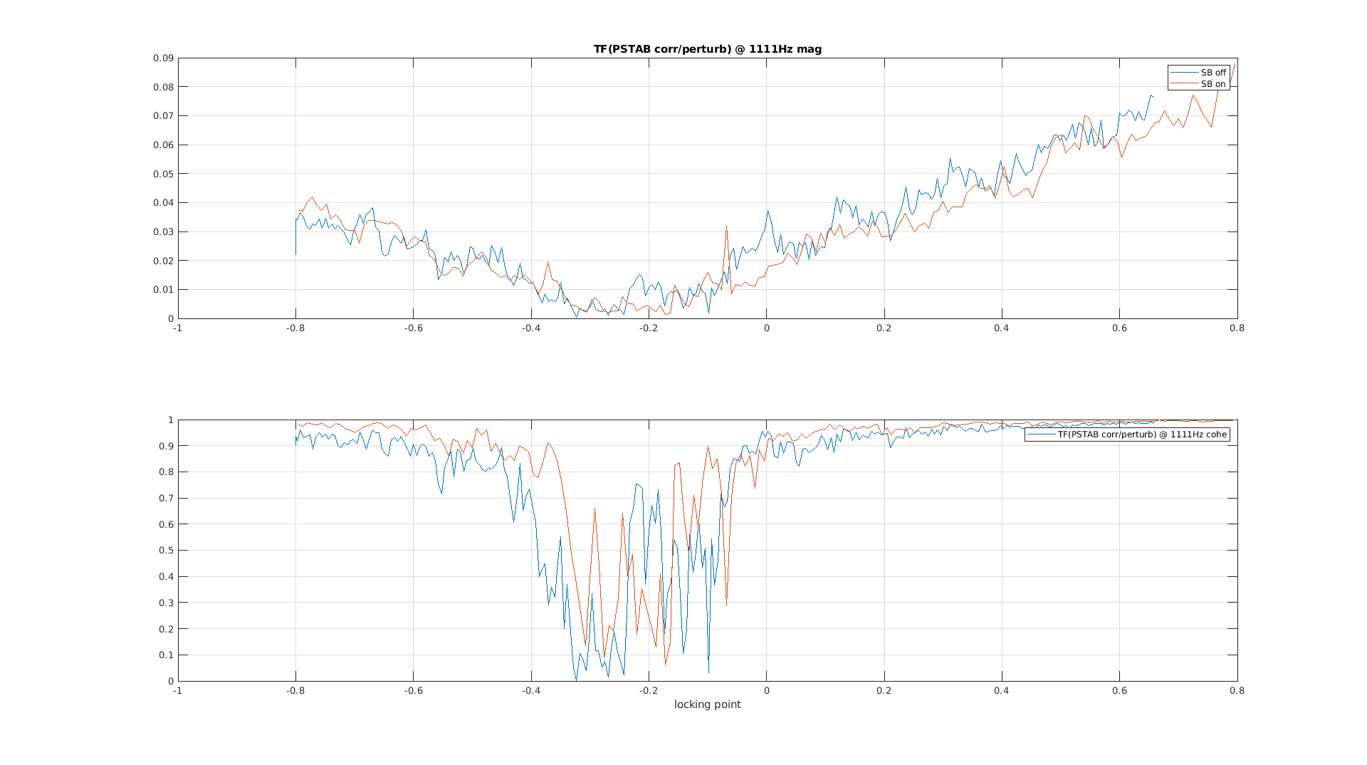
We switched on again the sidebands in order to check if they had an influence of the working point of the IMC.
10:00:00 scan +- 0.8 V
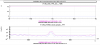
The sidebands do not seem to have an influence on the working point. (figure 2)
BsX_ML_PZT
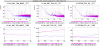
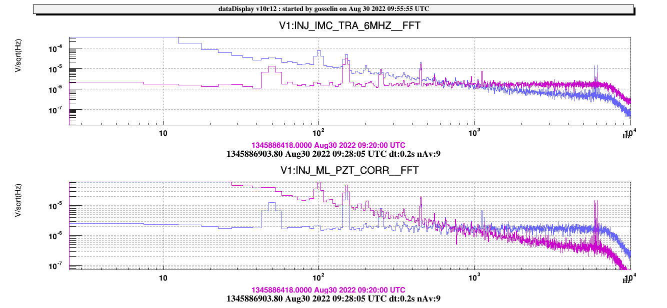
While switching on the 1111 Hz line we noticed that it was not visible in the correction send to the PZT of the ML.
We had to increase it quite a lot to be able to see it.
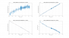
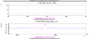
We investigated a bit and realized that there is no coherence between the error signal and the correction. The monitoring channel reading the PZT has a problem that will have to be adressed. (figure 3)
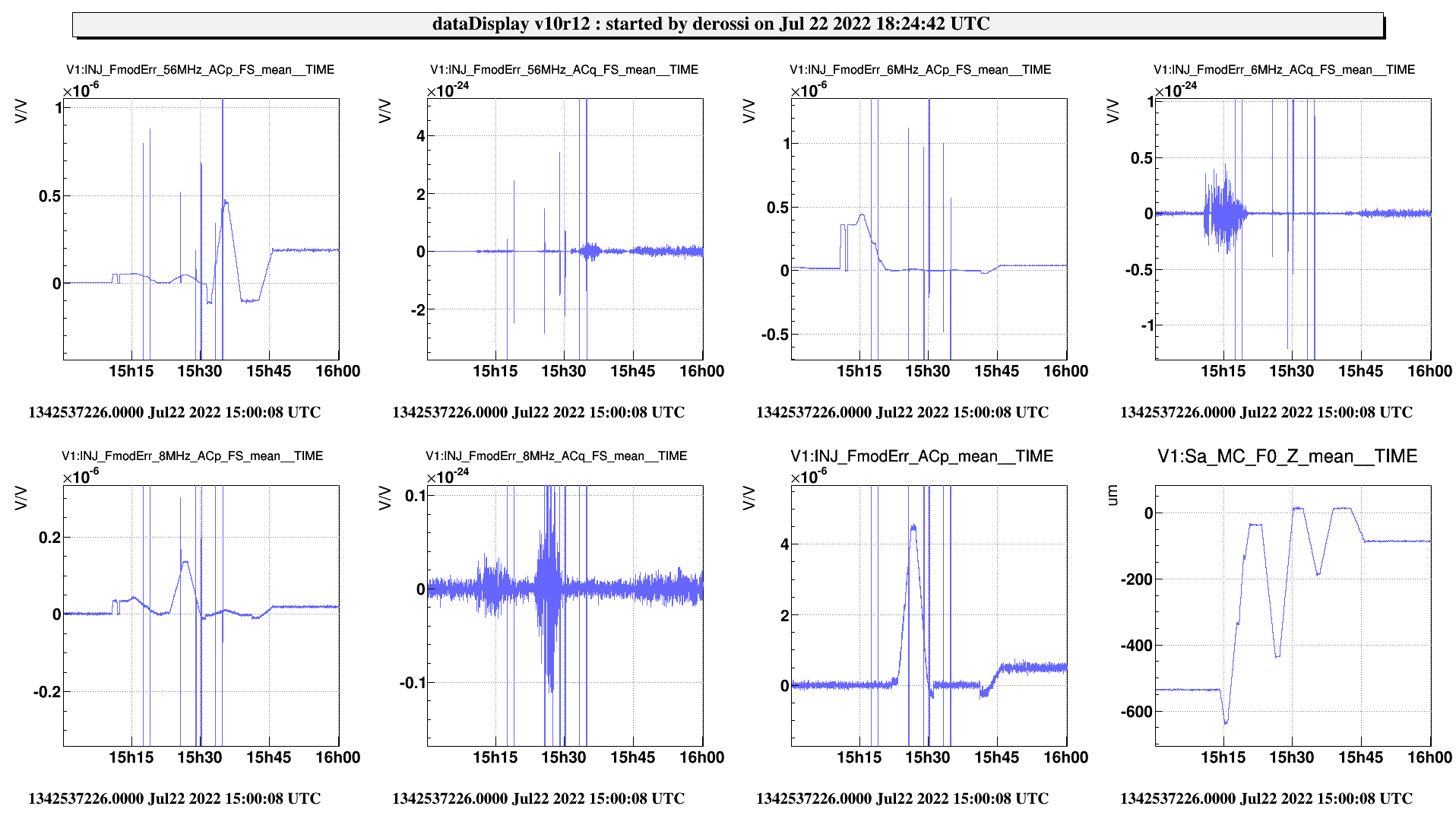
Fmoderr
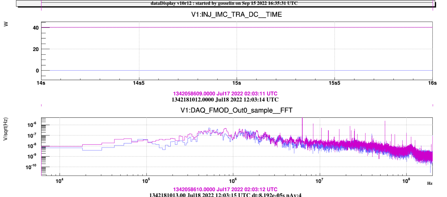
We asked Alain to demodulate the DAQ_FMOD_6MHz DAQ_FMOD_8MHz DAQ_FMOD_56MHz at 1111 Hz.
This is now done in ACL (EOM_demod)
The new created channels are :
INJ_FmodErr_6MHz_ACp
INJ_FmodErr_6MHz_ACq
INJ_FmodErr_8MHz_ACp
INJ_FmodErr_8MHz_ACq
INJ_FmodErr_56MHz_ACp
INJ_FmodErr_56MHz_ACq
The Acp signals should give us the same information than the error signal which currently used for Fmoderr.
We tried each signal with the other sideband switched off (ie -15 dBm)
The 1111 Hz line amplitude was set to 0.2.
6 MHz (12 dBm) at 15:14 UTC
8 MHz (0 dBm) at 15:27 UTC
56 MHz (12 dBm) 15:36 UTC
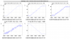
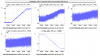
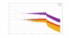
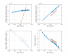
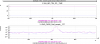
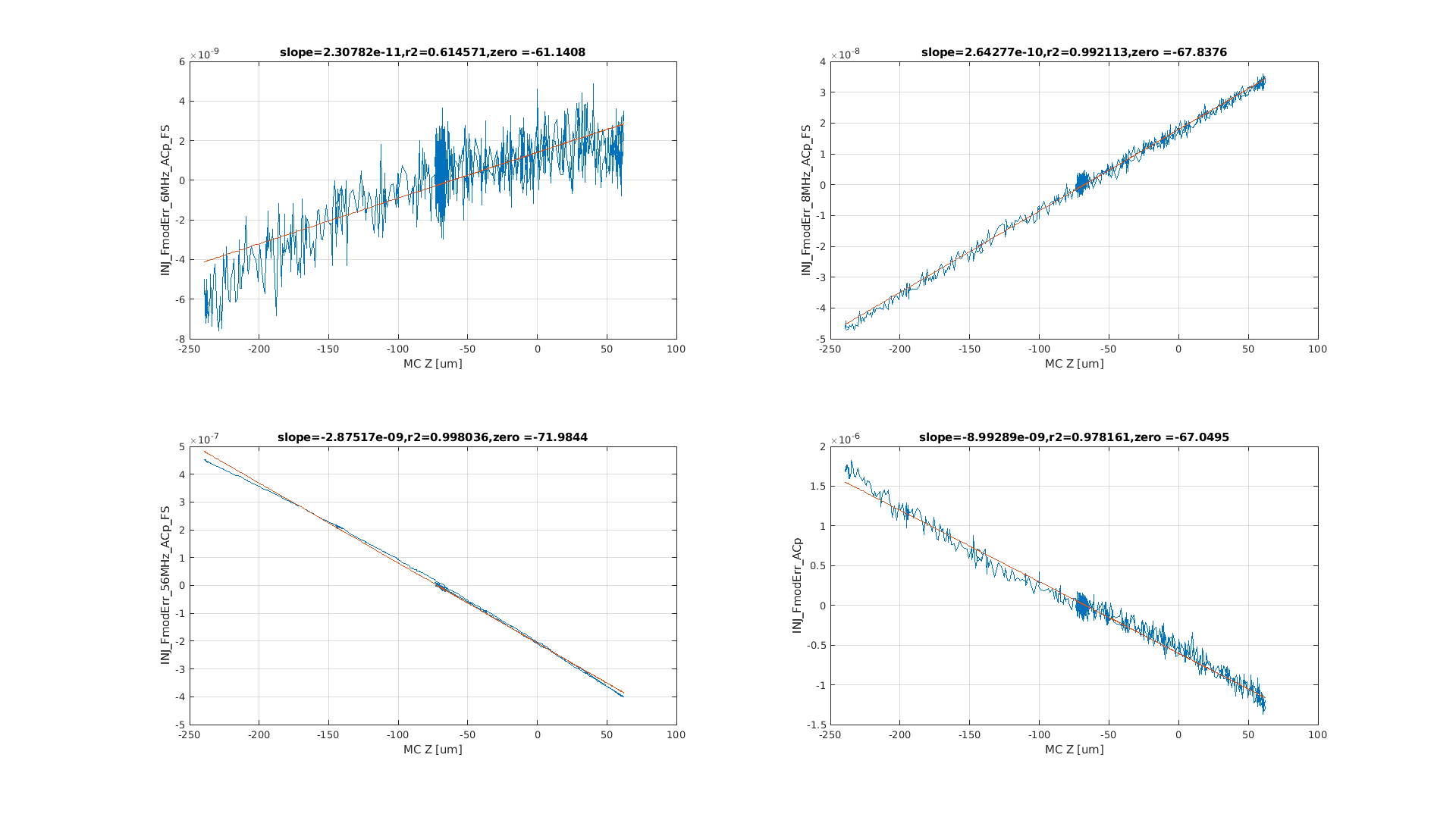
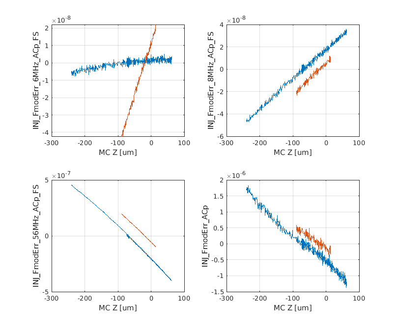
The different scans are shown in figure 4.
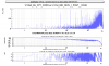
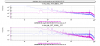
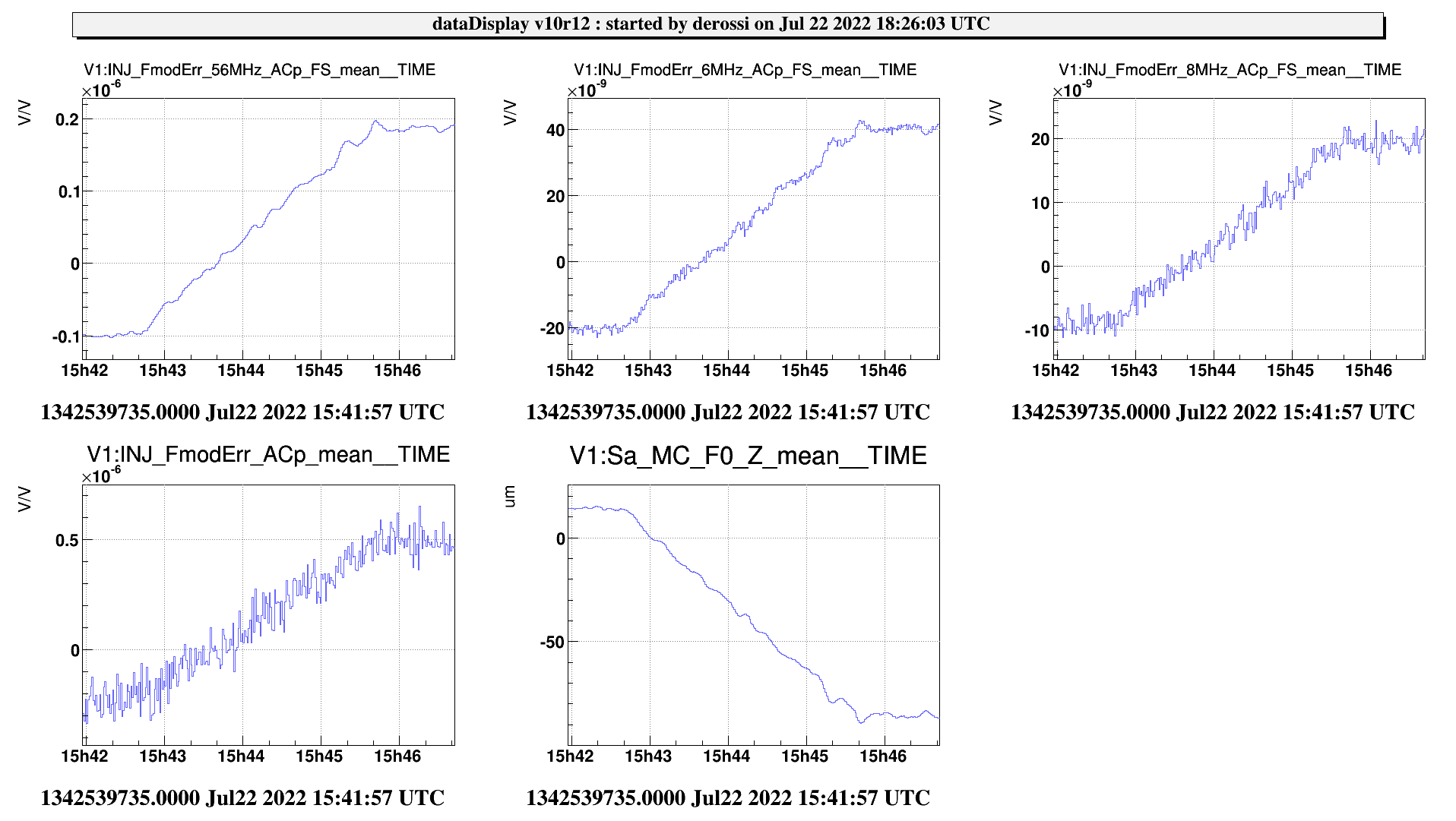
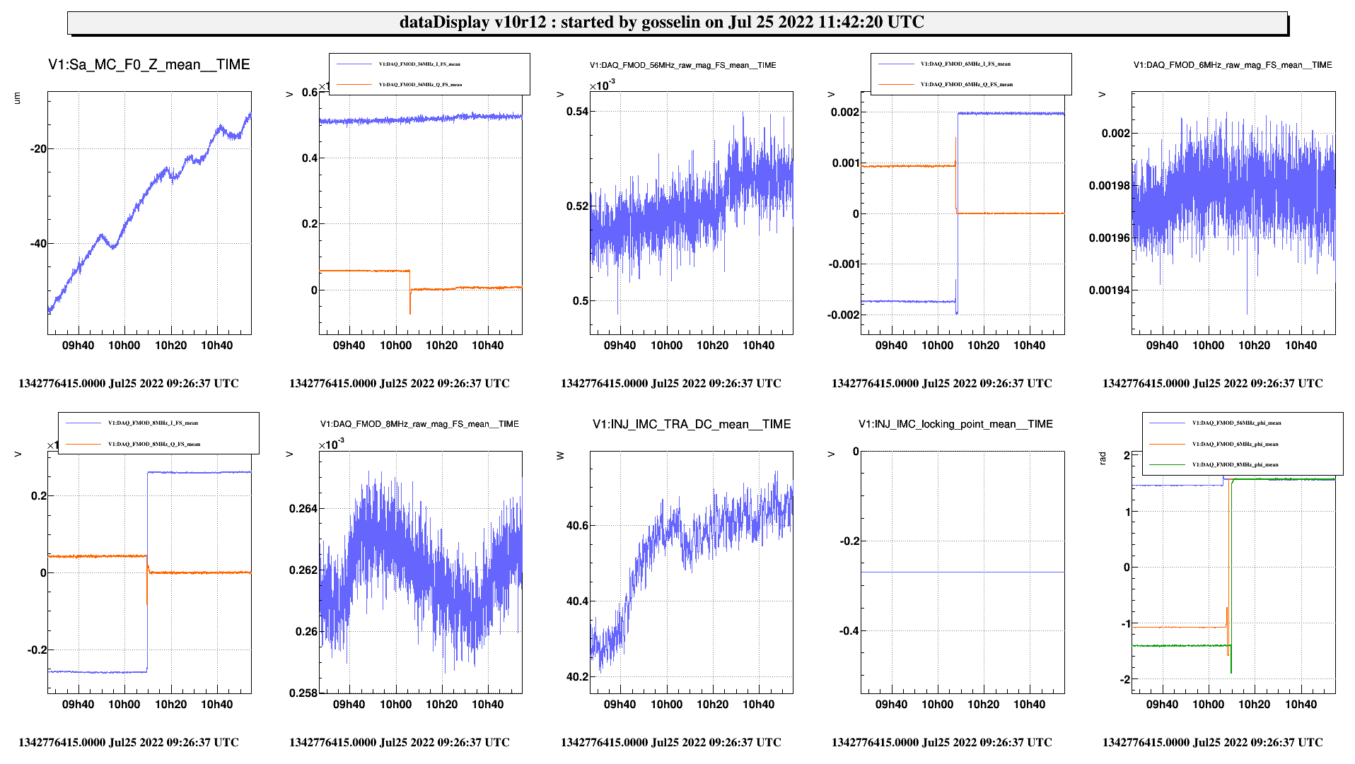
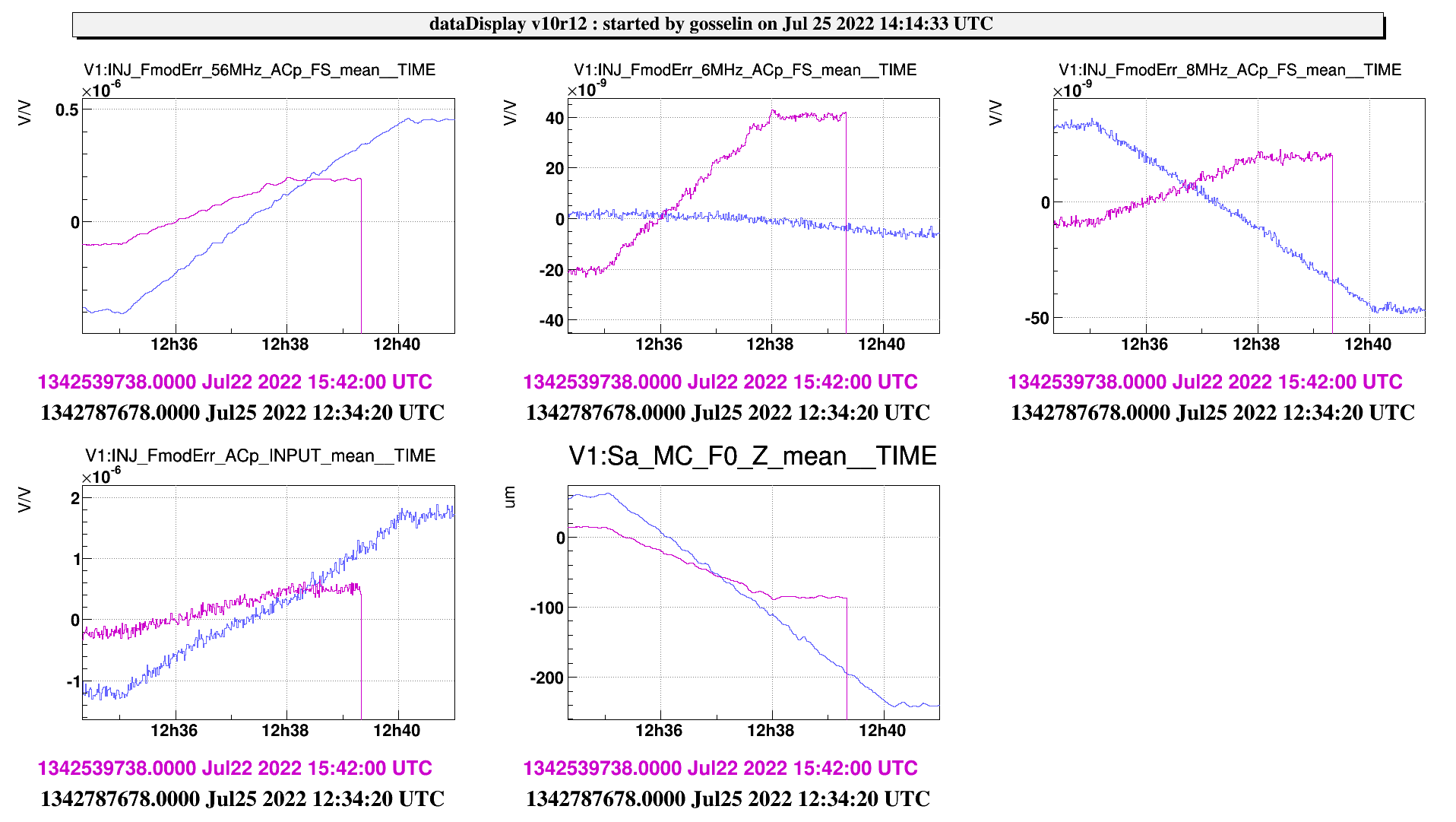
Then we switched on the 3 frequencies simultianeously and did another scan 15:42:39 (figure 5 trend, figure 6 raw)
We will better analyze the data but the new signals are much better than the one that was previously used (INJ_Fmoderr_Acp), especially the 56 MHz one.
Moreover they are all crossing 0 for the same MC position.
Additional tests
With all the 4 errors signals crossing zero for Sa_MC_MAR_Z = -20. This position of the mirror seems to be the one that ensure FSR=FMOD.
Having this information we wanted to repeat the tests that have been done in the previous shifts in order to better understand if we have RAM at the modulation frequencies.
First test:
No offset on the working point of the IMC.
1111 line off
Scan the MC around the right position and check the the magnitude of the DAQ_FMOD channels.
16:27:47 UTC scan of 300 s
Second test
Same than before put with an offset on the working point of the IMC.
17:36 working point to -0.07 V (fmoderr offset on the vpm)
17:43:50 scan (+200)
17:49:47 working point to 0.47 V
17:50:16 scan (-200)
17:56:58 IMC working point back to -0.27 V
The results of those last tests will be further analyze later.


