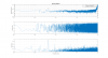
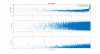
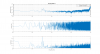
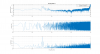
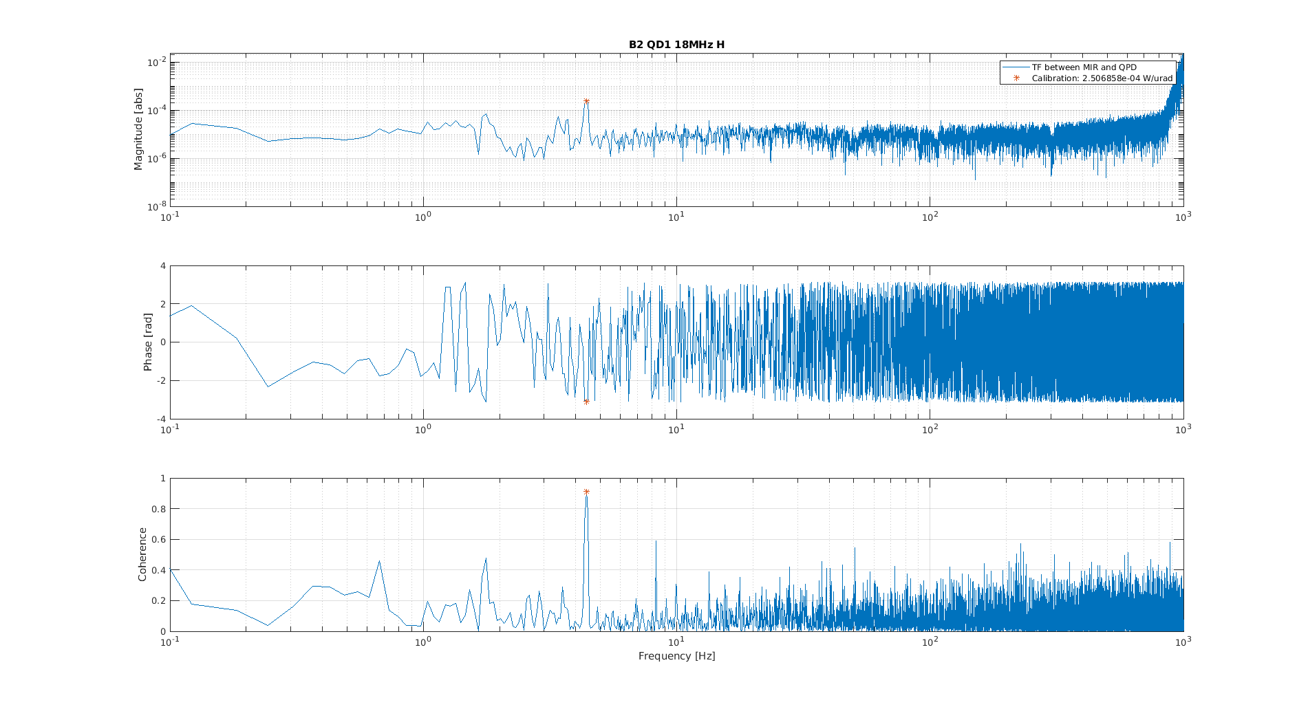
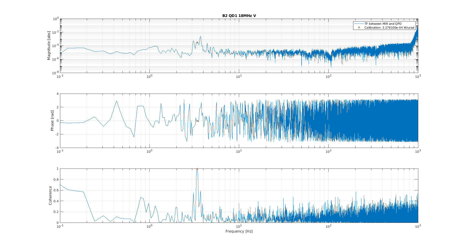
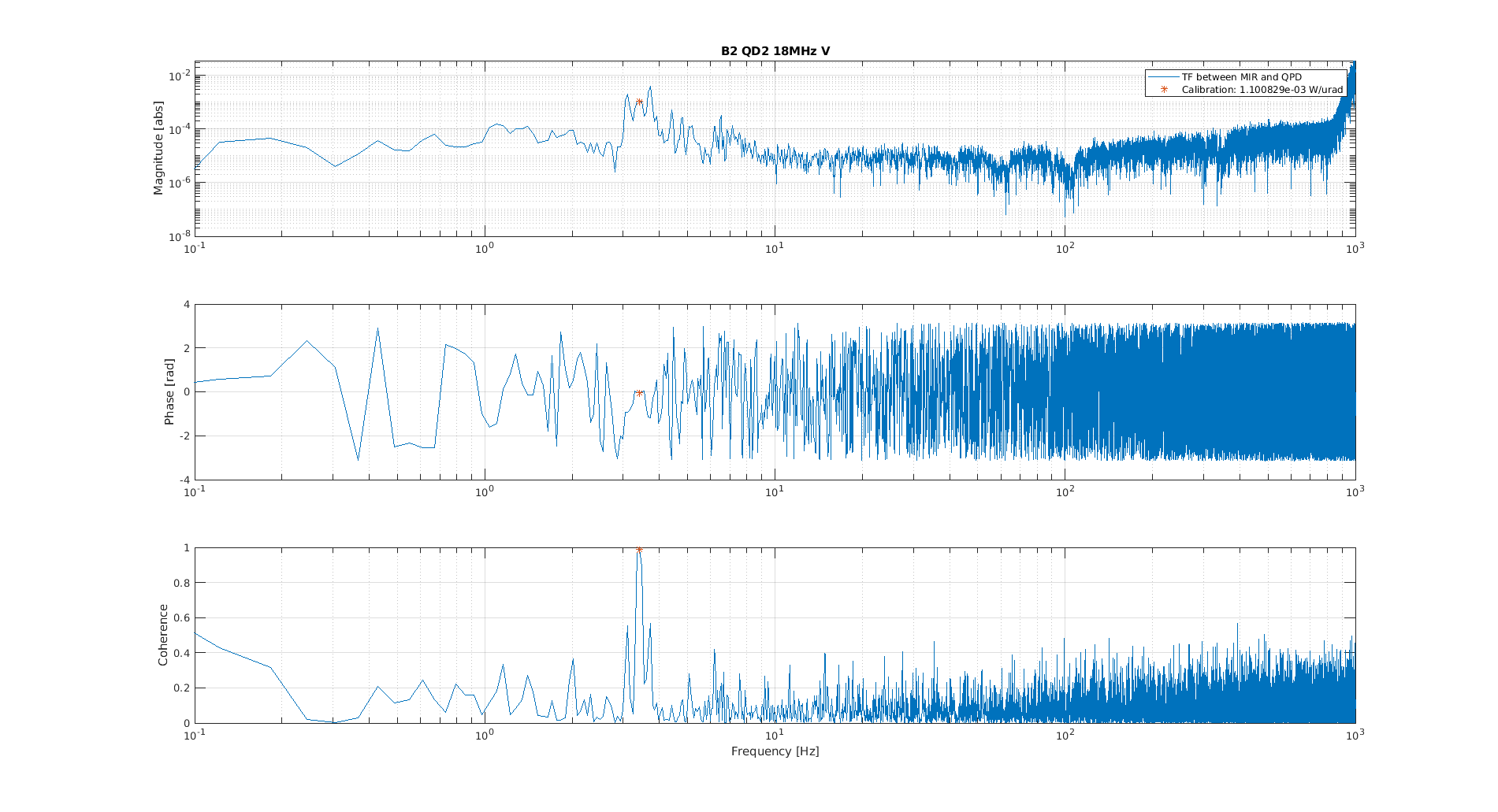
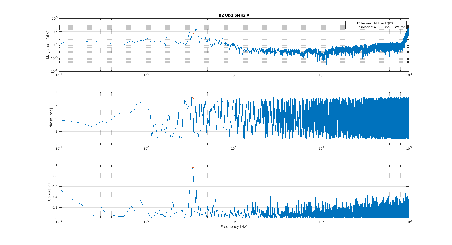
Using the angular lines that are injected to the PR mirror I have computed the optical gain of the corresponding error signals. The calibration is based on the Local controls readout signals of the PR mirror, which give the information in radiants already. The calibration has been made by making the transfer function between Sc_PR_MIR_T* and the corresponding error signal. We have checked both the 6MHz and the 18MHz signals. The coherence and optical gain is shown in Figures 1 to 8.
IN order to make a comparison with simulation, we have normalized the optical gans by the total power reaching the quadrants and then we have combined the information from both quadrants (sqrt(QD1^2 + QD2^2)), to remove the uncertainty on the gouy phase of the sensors. All the information is summarized in the following table:
| H | OG [W/urad] | OG norm [1/urad] | Combined OG [1/urad] |
| B2 6MHz QD1 | 8.2e-3 | 5.5e-2 | 0.39 |
| B2 6MHz QD2 | 6e-2 | 0.39 | |
| B2 18MHz QD1 | 2.5e-4 | 1.7e-3 | 3.4e-3 |
| B2 18MHz QD2 | 4.5e-4 | 3e-3 |
| V | OG [W/urad] | OG norm [1/urad] | Combined OG [1/urad] |
| B2 6MHz QD1 | 4.7e-3 | 2.7e-2 | 0.93 |
| B2 6MHz QD2 | 1.7e-1 | 0.9 | |
| B2 18MHz QD1 | 3.3e-4 | 1.9e-3 | 6.4e-3 |
| B2 18MHz QD2 | 1.1e-3 | 6.1e-3 |


