• At 10: 50 LT lowered the supply air-fan inverter frequency from 40 to 35 Hz
• At 12:50 LT modified the saturation temperature PID increasing the Integral time from 2 min. to 20 min.
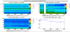
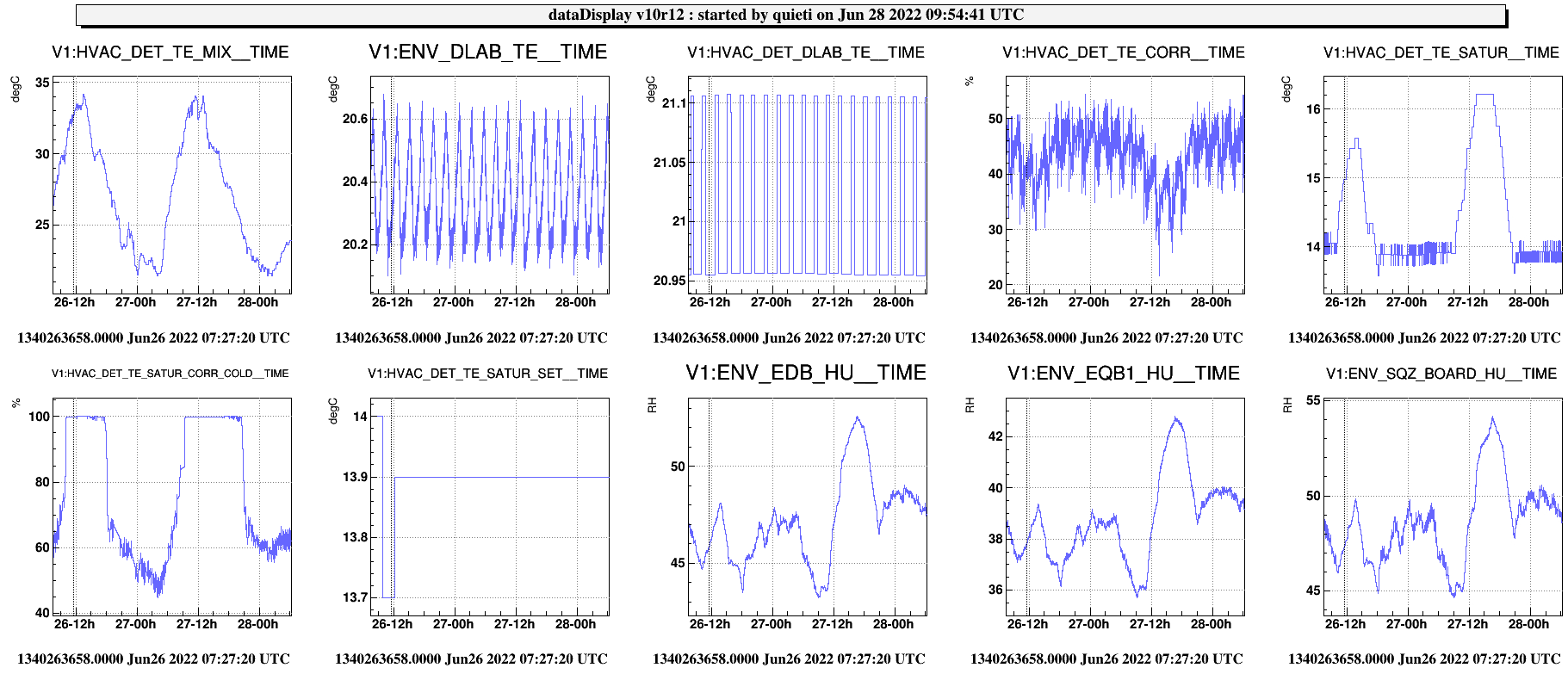
Concerning the monitoring of the recent actions (elogs. 56260 and 56266), I attach a trend of relevant signals for from 26h June (1st figure).
The cold “saturation temperature” control becomes saturated whenever the temperature inside the AHU Mixer (HVAC_DET_TE_MIX) exceeds the level of about 30 degC. The AHU Mixer is the point where the outside air is added and mixed with the circulation flow of the AHU. As a result, with the actuator saturated (cold-water valve fully open) the cold saturation temperature (VAC_DET_TE_SATUR) starts to rise, meaning that the dehumidification process at the cooling pipe heat exchanger weakens, and thus the humidity in DET-LAB increases.
To improve the performances of the AHU the external air damper, which regulates the flow inside the AHU Mixer, has been reduced from 10% to 5% of its entire range (see elog. 56270). This action added to a previous optimization of the condensation water discharge below the cooling coil, and to the last reduction in the frequency of the supply air-fan, should increase the overall humidity control. In any case, the problem of the saturation of the cold-water valve will arise whenever the external air temperature will exceeds a certain temperature difference DT compared to the DET Lab temperature (set point 21 degC). At present this DT appears to be ~ 9 degC.
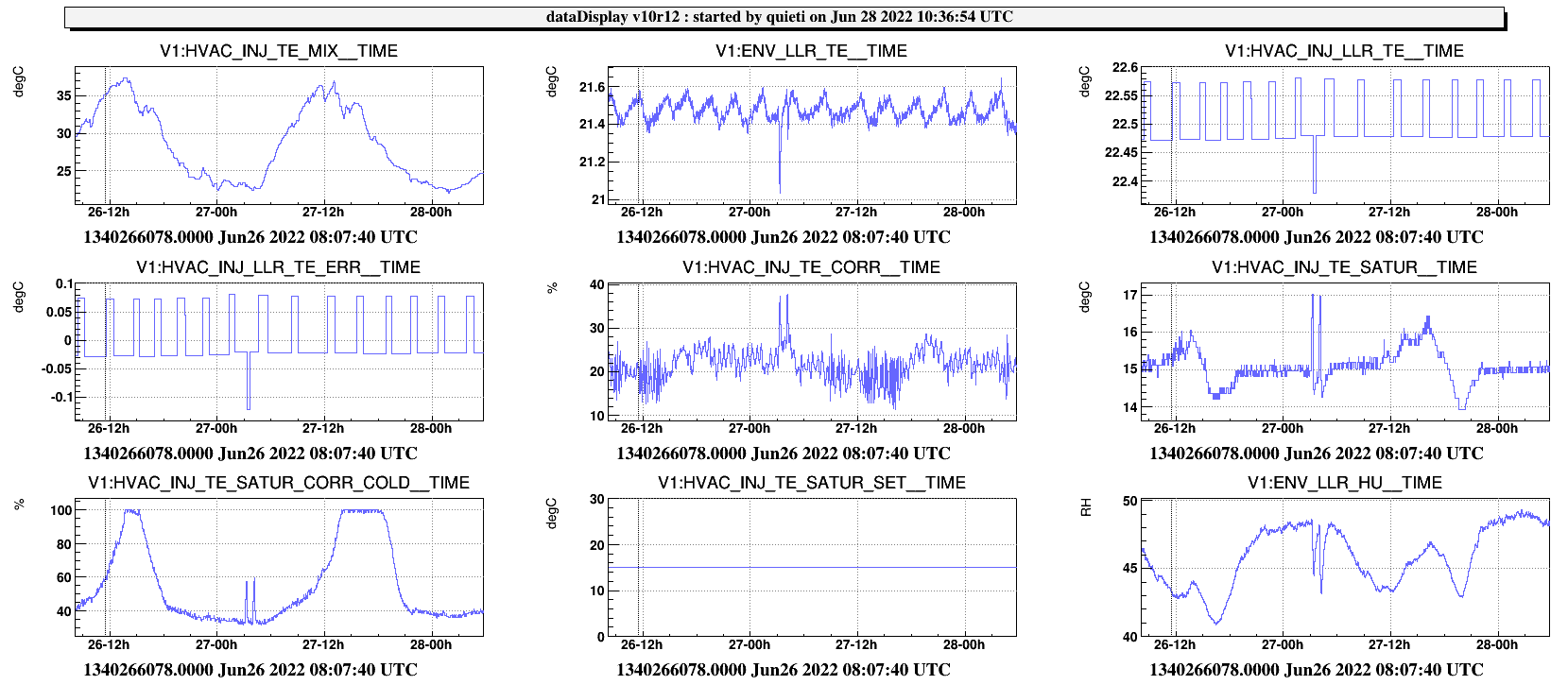
For comparison, in the 2nd attached figure is the same temporal trend for the “twin” AHU that manages the INJ-LAB.
As it appears, also in this case the “air saturation control” saturates but later and at a higher temperature threshold in the AHU Mixer. This probably because the heat exchange of the air flow on the AHU cooling-coil is better than on DET-AHU. In fact the air supply fan inverter could be set in this case just at 25 Hz.
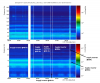
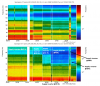
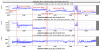
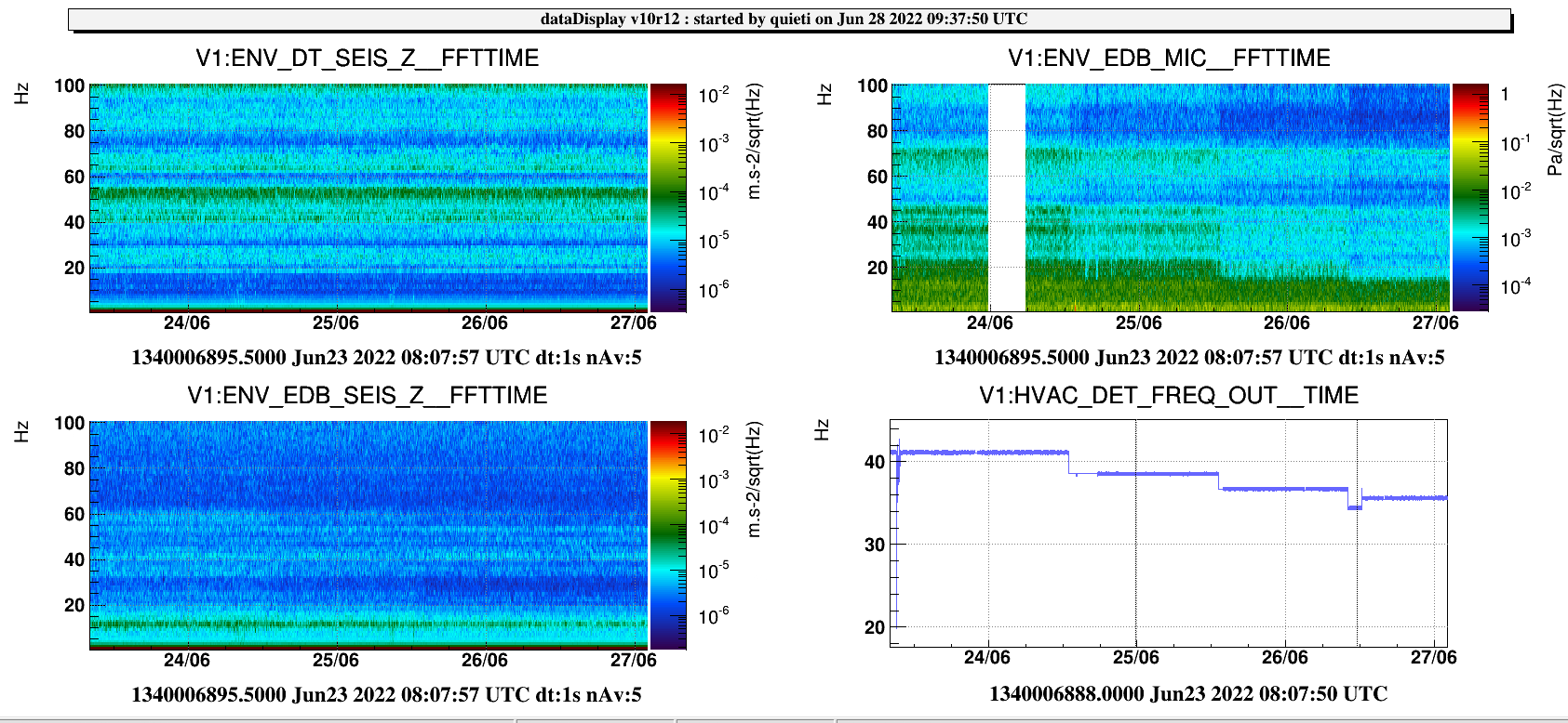
Finally, In the 3rd attached figure is the spectrograms from the microphone signal ENV_EDB_MIC in DET-LAB, and seismometers ENV_DT/EDB, spanning all the reported frequency reductions of the supply air-fan inverter, except the last one today. Each actions, made evident by the steps in the frequency signal of the air-supply fan (HVAC_DET_FREQ_OUT), is followed, as side effect, by a reduction of the acoustic noise in DET-LAB, I suppose also accompained by a seismic noise reduction to be better checked.
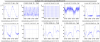
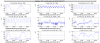
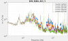
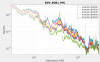
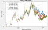
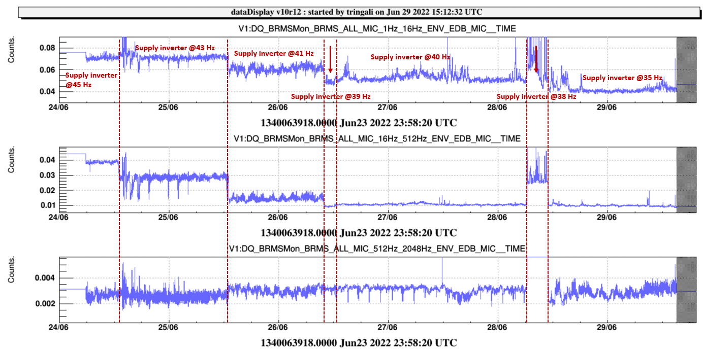
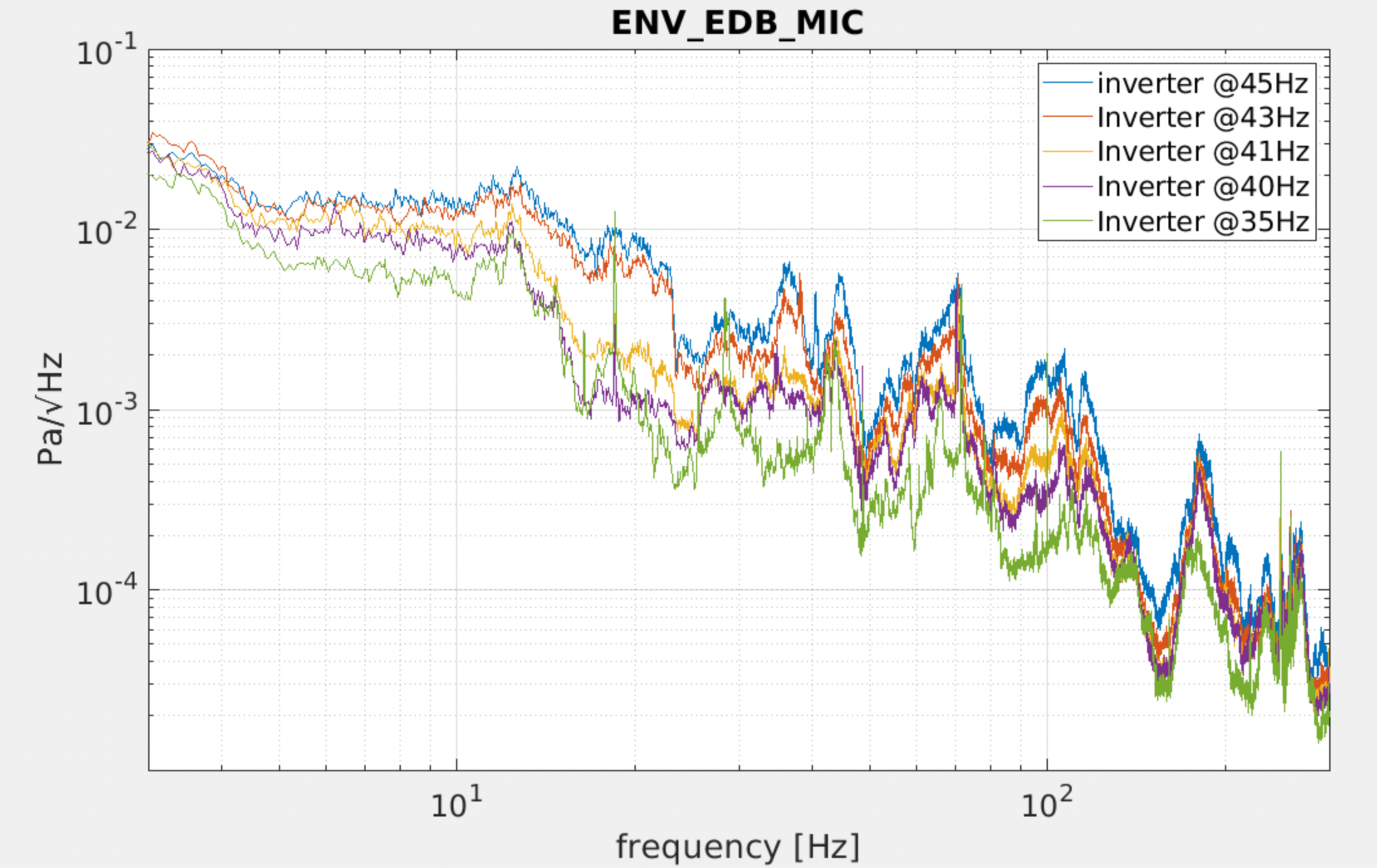
The spectrograms of the microphone (ENV_EDB_MIC) and accelerometer (ENV_EDB_ACC) make in evidence the acoustic and seismic noise variations in DET-Lab after the last actions to set-up the supply inverter frequency of that air handling unit (AHU), Figure 1 and Figure 2. In both spectrograms, a significant noise reduction is visible after each inverter frequency reduction action. The rms signal of the microphone shows a noise reduction of about 40% in the band (1-16)Hz and of about 70% in the band (16-512)Hz having set up (step by step) the supply inverter frequency from 45 Hz to 35 Hz, Figure 3.
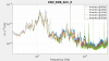
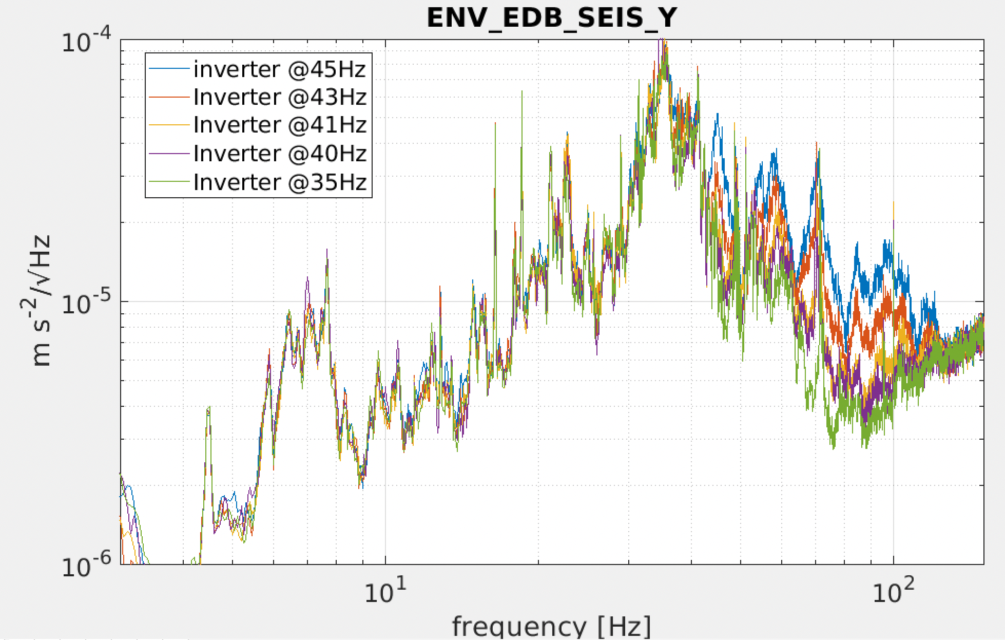
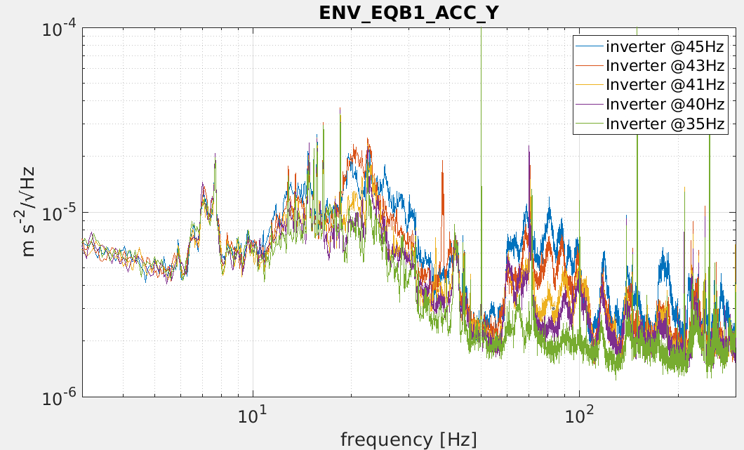
Moreover, the evidence of noise reduction is visible also in the other attached Figures concerning the acoustic and vibration sensors, also in the squeezing area (ENV_EQB1*). General important noise mitigation was achieved in the bandwidth ~(10-100) Hz, Figure 4, 5, 6,7, 8.
More analysis will follow.
