Today we kept the work on the stray light loop. We wanted to close the stray light loop and the CC loops together.
The filter cavity lock precision was ~1Hz. The cavity has been aligned on the IR reaching 14.5 V in transmission.
Stray light loop + CC loops
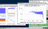
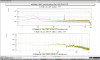
At 9h43m30 UTC we closed the loops (5 mins of data):
Gain CC fast = 100
Gain CC coarse = 0.5
Gain Stray loop = 5000
CC phase = 0.8 (ASQZ)
In Fig. 1 the signals. We notice that we are introducing a servo bump ~100 Hz. So we tried to reduce the gain of the stray loop.
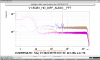
We took some data, see Fig.2 :
9h50m14 UTC : shot noise (IR shutter closed) in magenta
9h54m04 UTC : CC loops closed (ASQZ, detuning FC 180 Hz), stray light loop open in yellow
9h58m11 UTC : stray loop + CC loops (ASQZ, FC detuned by 180 Hz) in blue - we notice that we are killing the FDS hole using the stray light loop.
We decreased the gain of the stray loop from 5000 to 4500 (10h07m12 UTC). There was an interplay between the two loops, introduced by the extra phase noise introduced by the stray loop dither line at 500Hz.
500Hz line compensation with M1 LO
So we decided to go on with the compensation of the 500Hz line on M4, acting on LO_M1. We had lots of troubles due to the micro seismic activity, that was introducing a phase shift too large to be corrected with the range of our actuators (CC fast on AEI shifter and CC coarse on M1 and M2).
We set the amplitude of the dither line on M4 at 10mV, to avoid sending a line too large on M1. In fact with 15mV we needed to set ~200mV to L1 to compensate the line, and it was unlocking the CC loop.
The final parameters are:
- Dither line M4_Z @ 500 Hz, 10mV
- Compensation line LO_M1 @ 500Hz, 80mV.
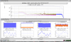
The compensation of the line is shown in Fig.3. We are limited by the line at 2kHz, whose origin is not clear to us. It is also present in the MAIN PLL channel. We will further investigate it in the next days.
Tune of the stray light loop gain to avoid the servo bump
We further decreased the gain of the stray light loop and we took some data:
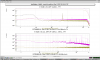
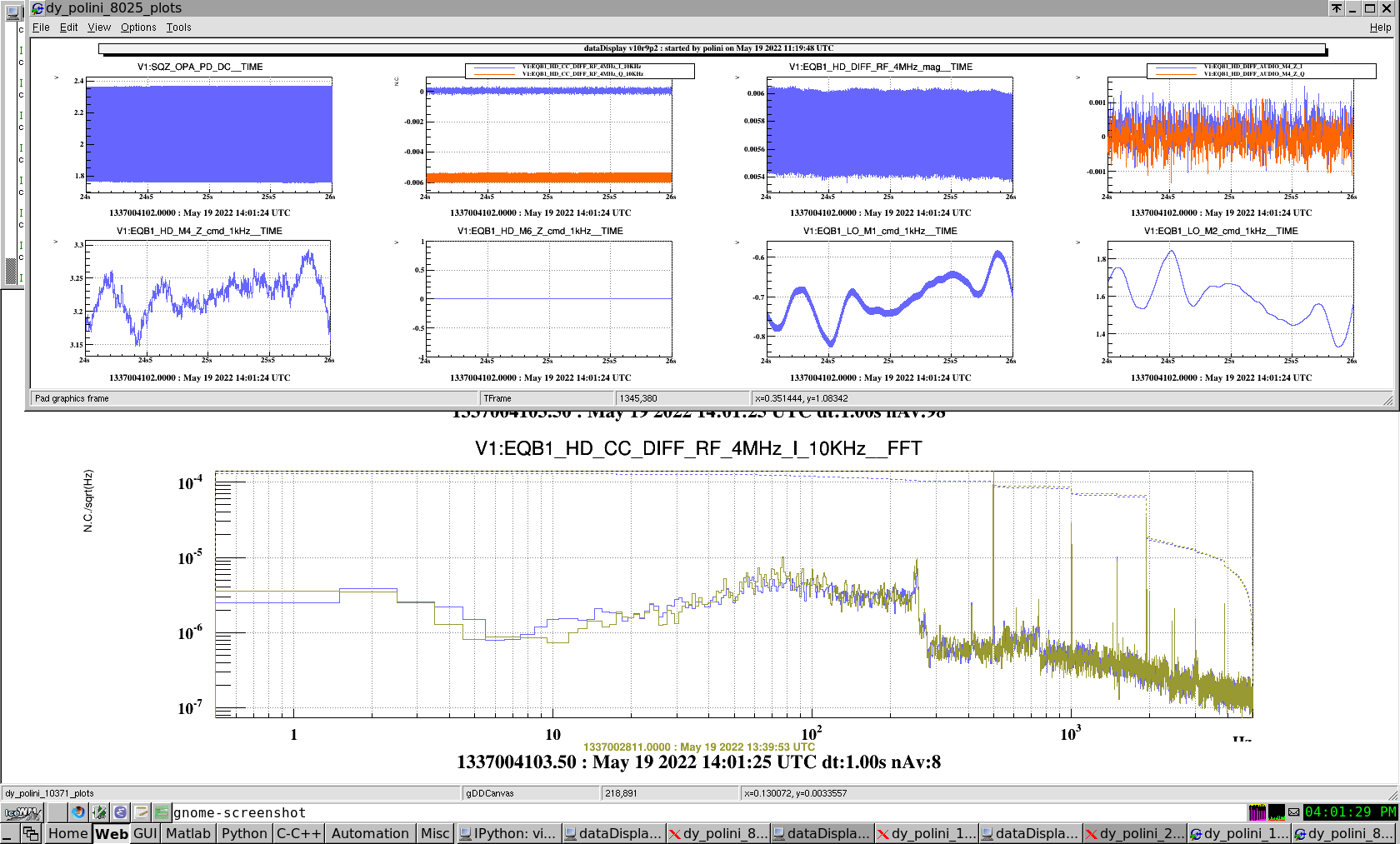
- Gain = 1500 @ 14h20m57 UTC, detuning at 180 Hz, stray light loop closed and CC loops closed for 5 mins - in Fig. 4 and 5 we see that we are touching the shot noise (yellow it is only CC loops on)
- Gain = 1200 @ 14h25m20 UTC, detuning at 180 Hz, stray light loop closed and CC loops closed for 3 mins
We kept the gain = 1200.
The line at 500 Hz on the CC error signal channel, was oscillating because the correction of M1 was moving a lot. So we turned off this actuator, using the M1 only for the compensation. It was better.
Stray loop + CC loops at different detunings
- detuning 130Hz @ 15h24m00
- detuning 80Hz @ 15h24m47
- detuning 160Hz @ 15h27m20 (1 min)
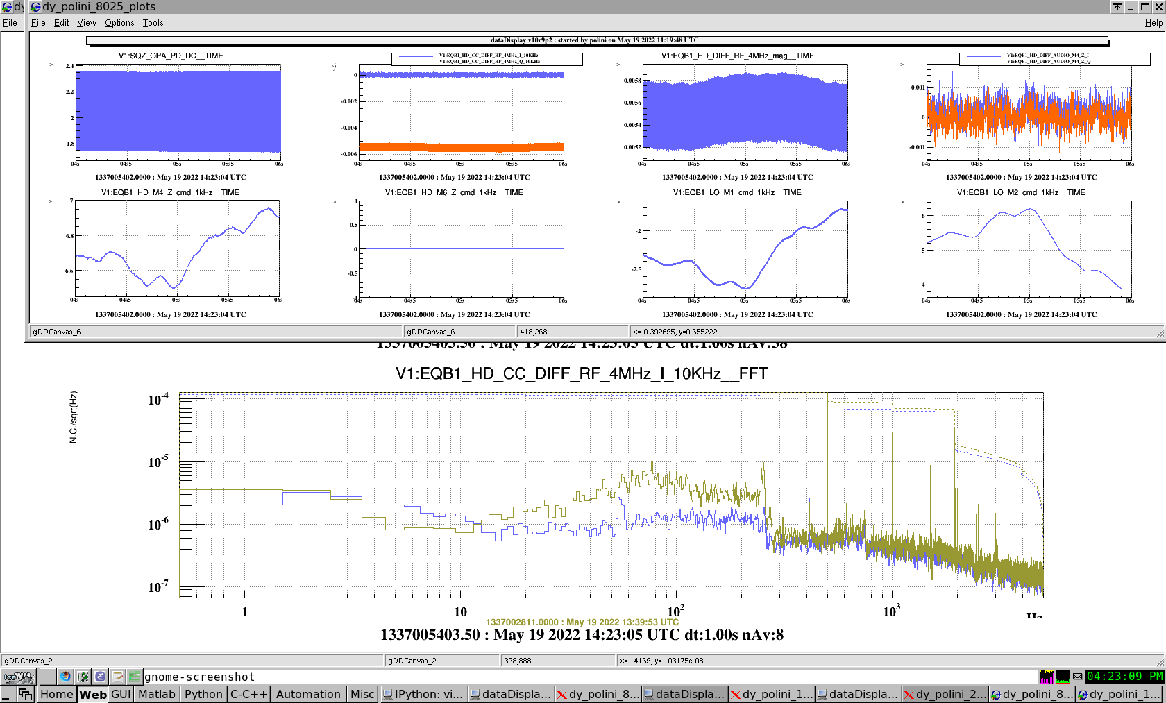
- detuning 100Hz Fig. 7
- stray ON + CC ON @ 15h28m44 (magenta)
- stray ON + shot noise (only LO) @ 15h37m04 (2mins, yellow)
- stray OFF + shot noise only LO) @ 15h39m24 (2mins, green)
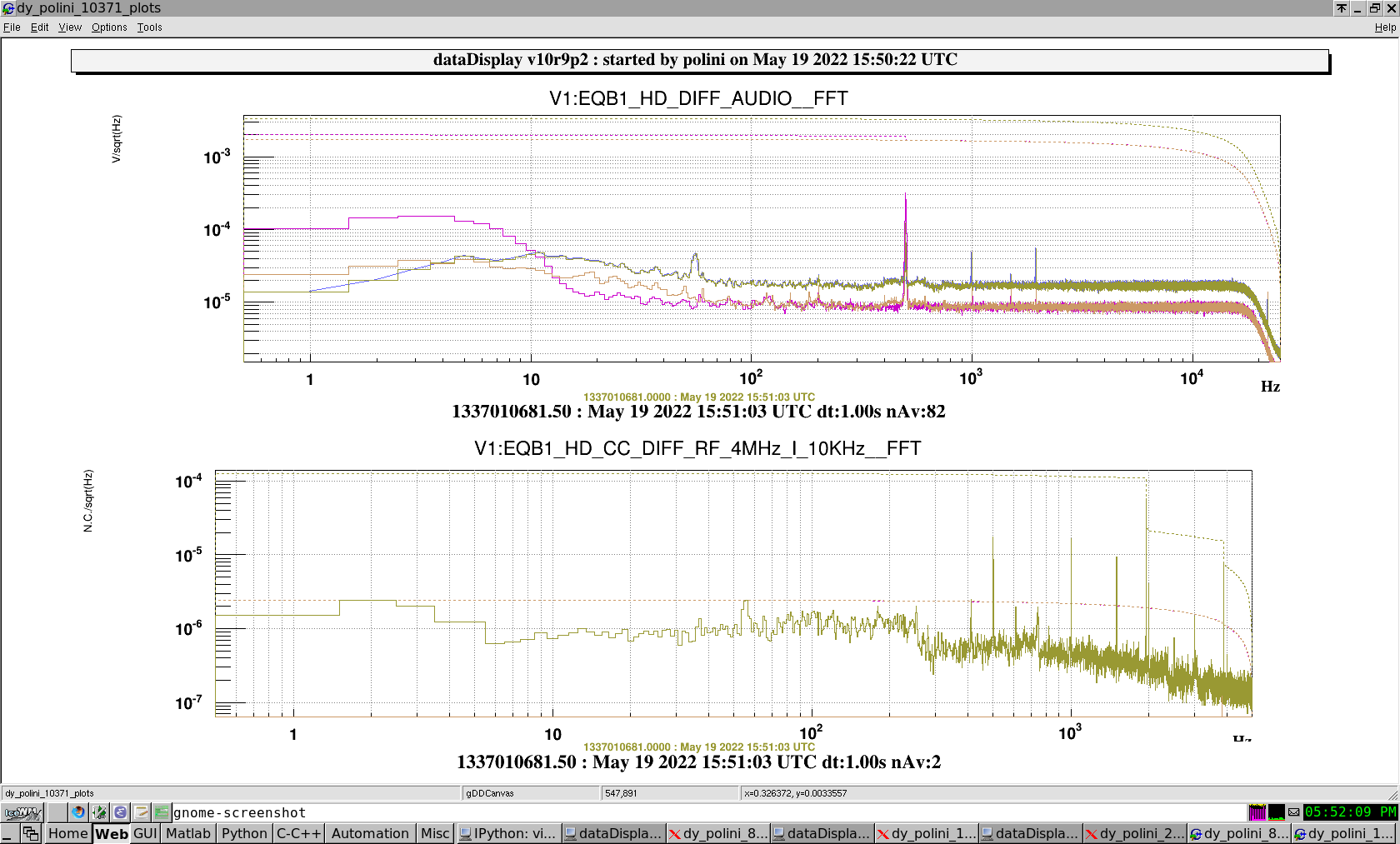
- detuning 50Hz Fig. 8
- stray OFF + shot noise (only LO) @ 15h43m30 (magenta)
- stray ON + shot noise (only LO) @ 15h45m00 (yellow)
- stray ON + CC ON @ 15h48m50 (green)
We conclude that
- the loops are working together;
- we need to tune the filter of the stray loop in order to see the hole on ASQZ when it is closed: because we are introducing a small servo bump at tens of Hz;
- we are no longer exciting peaks at tens of Hz when closing the stray light loop.

