Following a discussion during the squeezing meeting of this morning where Fiodor pointed out that the control of TX dof of SQB2 was a bit noisy, I worked on tuning the filter for this loop around lunch time.
After trying to only change the gain of the loop without too much success, I changed a bit the filter from :
# nameFlt - rampTime - gain - freq - maxOrder
ACL_FILTER_SET "flt_TXZ" 1 -0.07 0.5 20
# good filter
# nameFlt - freqCut Q ...
ACL_FILTER_POLES "flt_TXZ" 4 0 0 0 2 0
ACL_FILTER_ZEROS "flt_TXZ" 0.1 0 1 0 0.15 0
ACL_FILTER_POLES "flt_TXZ" 3 0.88 5 0.88 7 0.88
ACL_FILTER_ZEROS "flt_TXZ" 10 50 15 50 20 50
to this :
# nameFlt - rampTime - gain - freq - maxOrder
ACL_FILTER_SET "flt_TXZ" 1 -0.19 0.5 20
# good filter
# nameFlt - freqCut Q ...
ACL_FILTER_POLES "flt_TXZ" 4 0 0 0 2.4 0
ACL_FILTER_ZEROS "flt_TXZ" 0.1 0 1.2 0 0.15 0
ACL_FILTER_POLES "flt_TXZ" 6 0.88 10 0.88 10.5 0.88
ACL_FILTER_ZEROS "flt_TXZ" 20 50 30 50 40 50
What I did is that I increased the gain at low frequency (below a few Hz) and shifted the cut-off part of the filter to higher frequency from 3 Hz to 6 Hz.
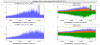
Figure 1 shows the error signal and correction signal of SQB2_LC_TX, one can see a reduction of the movement of the bench (SQB2_LC_TX_err) up to 1.5 Hz, a small bump up to 4 Hz compared to before (purple line) due to a higher correction sent between 1.2 Hz and 20 Hz (see SQB2_LC_TX_corr).
The shifting of the cut-off part of the filter is responsible for the higher correction above 1.2 Hz but it gives some phase margin to the loop and allowed to increased the gain at low frequency while avoiding an instability of the loop located around 1.4/1.5 Hz.
One could think about a better filter to keep enough phase margin at 1.5 Hz to increase the gain at low frequency a dumped correctly the 0.4 Hz oscillation while not reintroducing too much correction above a few Hz.
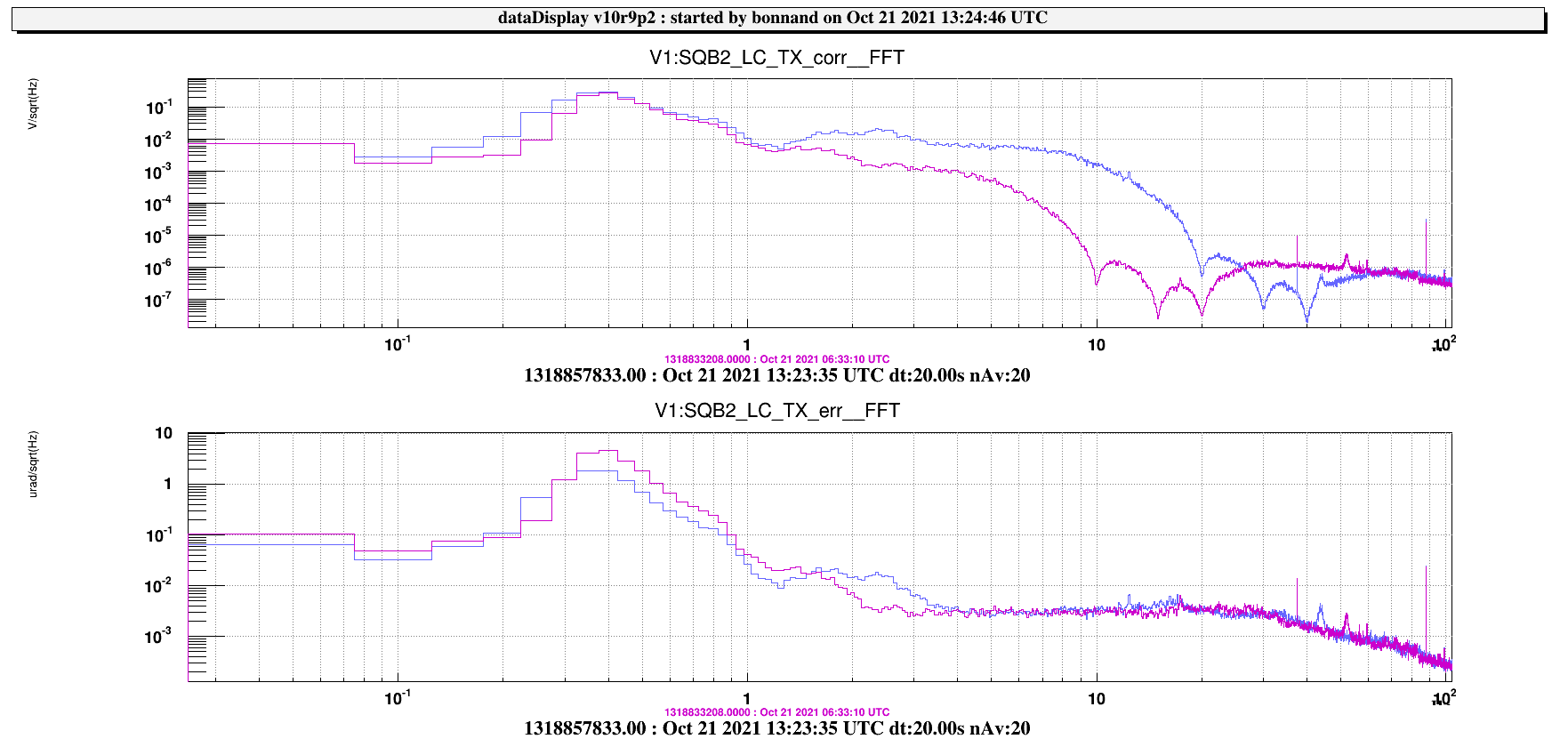
Figure 2 shows the rms and trend data of the SQB2_LC_TX signal, we can see that the RMS of the signal is reduced after the tuning was completed a few minutes after 12:00 UTC.
SQB1_LC_TX is also plotted for comparison.
I will monitor the loop for a few days to be sure the loop is stable in all condition.