Today we measured for the first time the SQZ reflected from the filter cavity. The MZ set was -0.05
Step 1: send IR to the filter cavity
- We switched SC
- We locked the SC PLL and the Int PLL
- We turned on the SC AA
- We rotated the HWP_2 in order to have a part of the power transmitted by the two FI toward the ITF
- We moved the IR mirrors M3_Mt1 and M5 in order to unclip the subcarrier reflected by the input of the filter cavity
- We checked the clip on the HD cameras and SQB1 Cameras
- We misaligned by 500urad in TY the end mirror of the filter cavity
Step 2: SQZ measurement preparation
- We close the CC fast and slow. Fast Gain 50
- We engaged the HD AA in order to superpose LO and CC with dither line amplitude 10 mV
- We moved IR_M3_MT1 and IR_M5 in order to maximize the magnitude i the homodyne detector with the AA closed IR_M3_MT1_X = -6.5V IR_M3_MT1_Y = 0 V IR_M5_X = -0.9V M5_Y = 0.2V
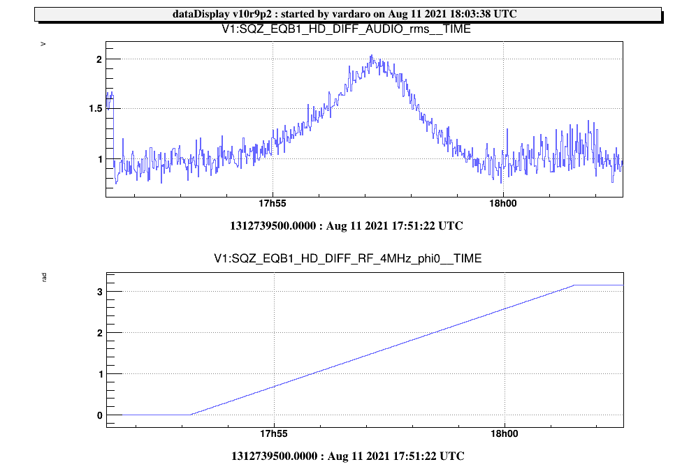
- We set the phase of HD DIFF RF 4 MHz demod phase at 0 deg
Step 3: SQZ Measurement
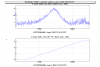
- Phase scan: 17:53 UTC
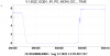
- 2 Mins of SQZ: 18:14 UTC
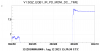
- 2 Mins of ASQZ: 18:18:30 UTC
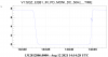
- Shot noise reference: 17:27:10 UTC and 18:22:30 UTC
- CC open phase noise: 17:32 UTC 2 min
SQZ Level = 1.9 dB at 2.55 rad
ASQZ level = 6.1 dB at 1.5 rad
Data will be analyzed