- The pick-off beam was measured @ 54mW, 41 mW after its reinjection -> 75%
- After the installation of the EOM, its output was 24mW -> 2.3 dB of insertion losses
- The pick off power was increased so to have the EOM output power @ 42mW, corresponds to 104mW @ pickoff ; The SL remained locked.
- The PMC was realigned to have a coupling efficiency of 89% (3% in the sidebands as usual)
Installation of the electronic box :
- The electronic box is powered by 24V provided by the power supply used by the PMC-rampauto
- The sign of the correction was adapted so the IMC can be relocked.
- The videodriver is still injected since it provides the EOM_corr monitoring signal. Its output was disconnected from the ultimate amplifier before the free space EOM, on the input of which a 50Ohm was connected.
Transfer function of the IMC loop :
- The gain of the new EOM electronic box was adjusted so the out of loop transfer function in the 1/f regime follows a smooth behavior (1/f) around the cross frequency (EOM/PZT) around 20kHz (see figure 1)
- On figure 1, the UGF is à 65 kHz. The gain of the loop was increased by 3dB (reducing the attenuation of the AC_in from 7dB to 4dB). The UGF was increased to 100 kHz(see figure2)
- After engaging the 1/f4 regime, the IMC is locked. The 1/f4 begins around 40 kHz but the TF saturates rapidly around 20 kHz. This is due to the behavior of the SR780 when high frequency components (sidebands frequency) is injected. By adding a 100kHz low bass filter to each of the measured signals, the measured 1/f4 behavior is brought down to 4kHz (see Figure3)
- To check that the 1/f4 regime is satisfactory (see Figure4), we measured the error signal in the 2 regimes. In figure4 the 1/f TF is compensating the 1/f2 behavior of the frequency noise (1/f of the NPRO and 1/f of the IMC acting as a filter ; or we might say that PDH error signal is a phase discriminator after the IMC pole)-> 1/f behavior. When we switch the 1/f4 regime, the error signal has f2 behavior as expected. However, there is an increase of the noise right after the 1/f4 frequency (a factor 2 to 3) which does not disappear when the gain is increased.
- No peaks was observed between 100kHz and 1MHz, except for the noise eater peak @ 680kHz which simply disappeared after restarting the noise eater. Note that this is then also observed on the laser frequency.
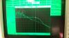
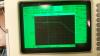
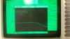
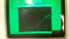
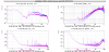
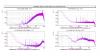
Figure 1 Compares some signals before (purple) and after (blue) the installation of the pigtailed EOM.
- The EOM correction shape is different, which may be normal as it is a different EOM, but it also seems to have much larger 50Hz. Up to a factor 10 higher despite the broadband noise being lower.
- The RFC error signal (so frequency noise after the IMC) is higher by a factor 3 in a broad region from 30Hz to 1kHz.
- There is some changes in the PSTAB in loop noise level, but the out-of-loop signal looks almost the same. This is probably just a reduction in the PSTAB loop gain by a factor ~2.
The RFC error signal noise increase should be investigated. It might be just the gain of the IMC loop that need adjusting, or it might be a sign of a bigger issue.
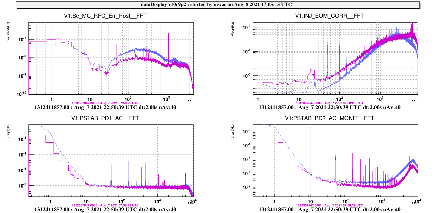
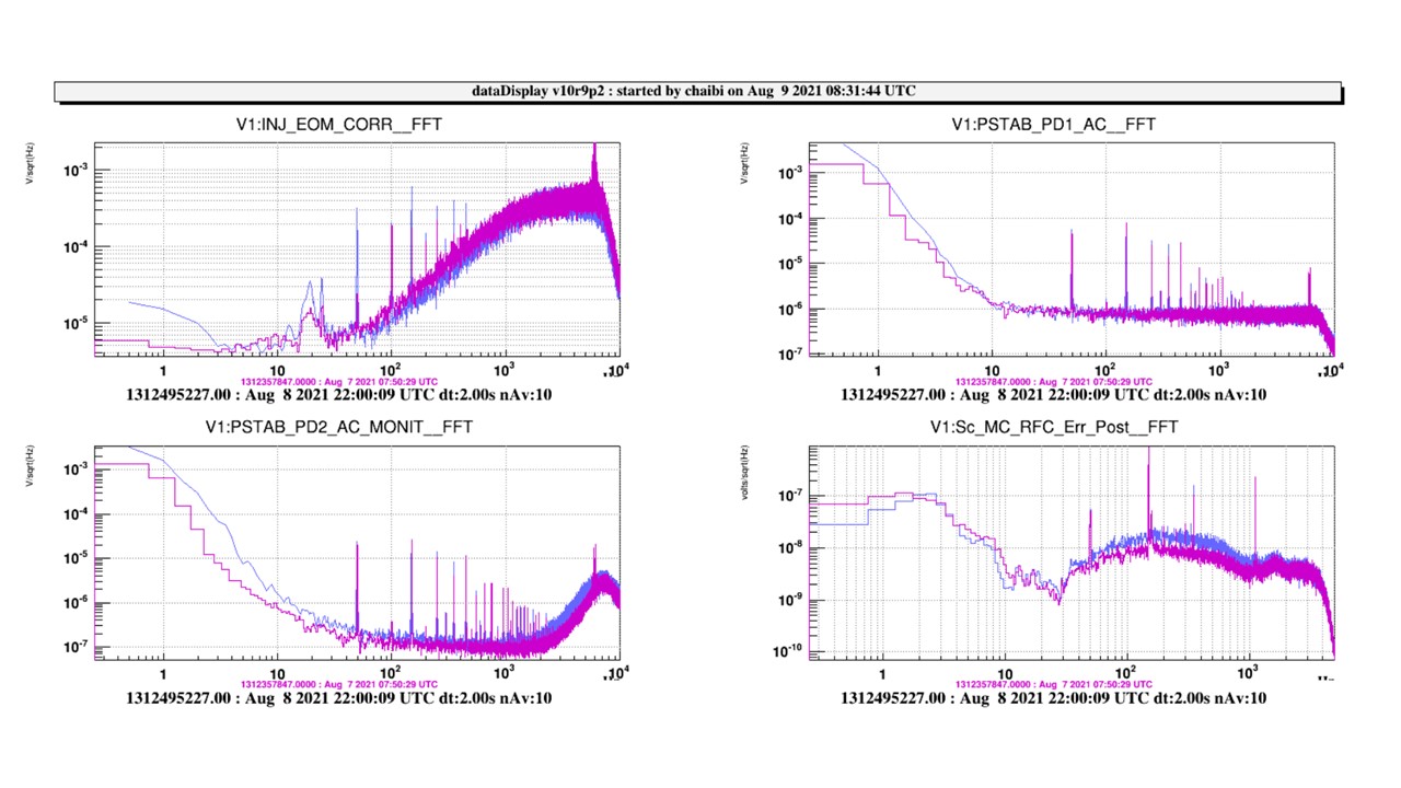
- The frequency noise on the RFC is closer to the initial value (less than a factor 2 higher). The gain needs to be slightly increased.
- The EOM correction has same shape. The increase of the 50Hz lines doesn't seem to appear on the frequency noise seen by the RFC so that might be real corrections injected to compensate the noise introduced by the free space electronics which is still connected to the last amplifier. It should be disconnected.
These points shall be discussed during the daily meeting.